Sound source separation device, speech recognition device, mobile telephone, sound source separation method, and program
a separation device and speech recognition technology, applied in the field of sound source separation devices, speech recognition devices, mobile telephones, sound source separation methods, etc., can solve the problems of significant deformation of estimation accuracy, increase of production costs, and inability to perform filtering well
- Summary
- Abstract
- Description
- Claims
- Application Information
AI Technical Summary
Benefits of technology
Problems solved by technology
Method used
Image
Examples
first embodiment
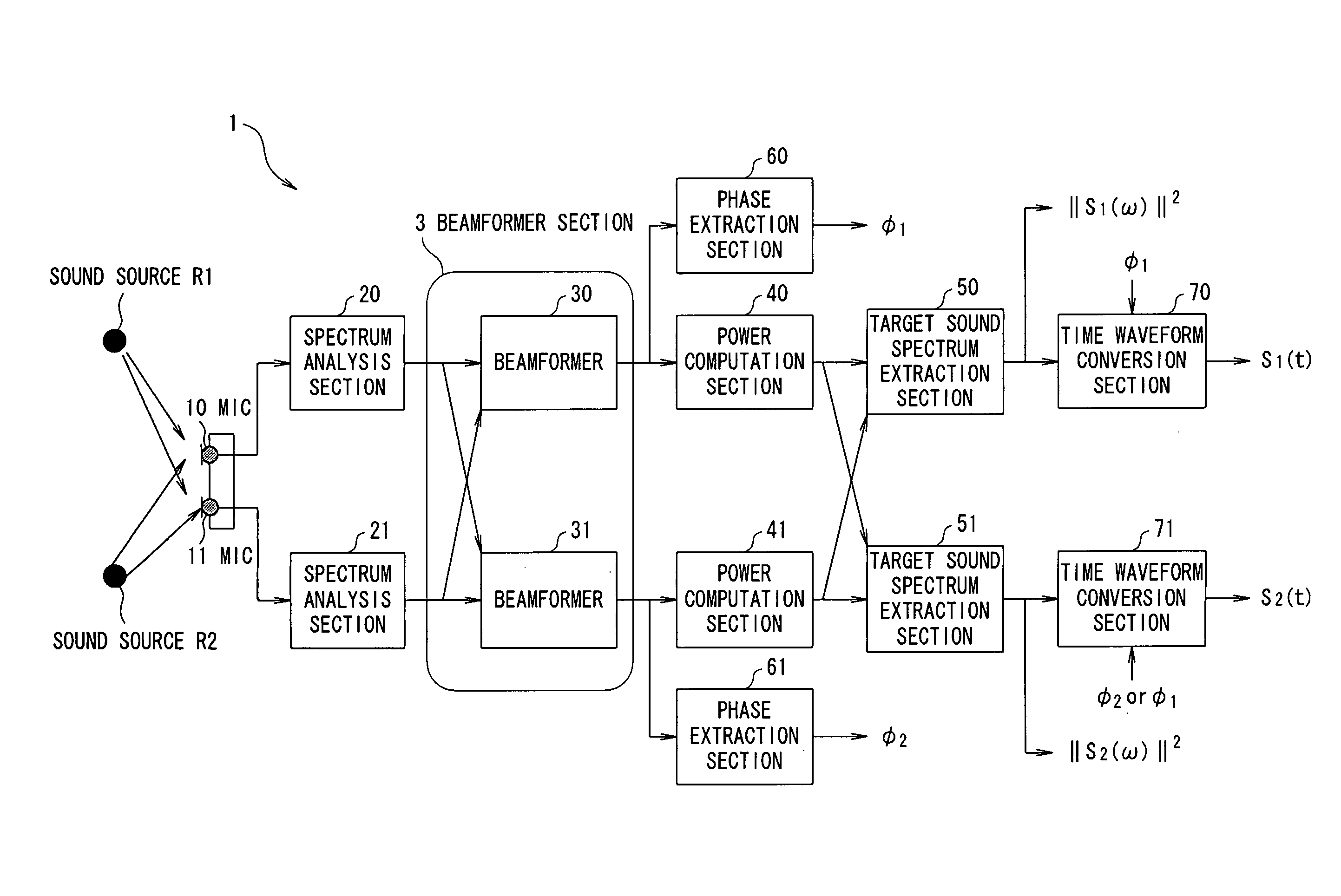
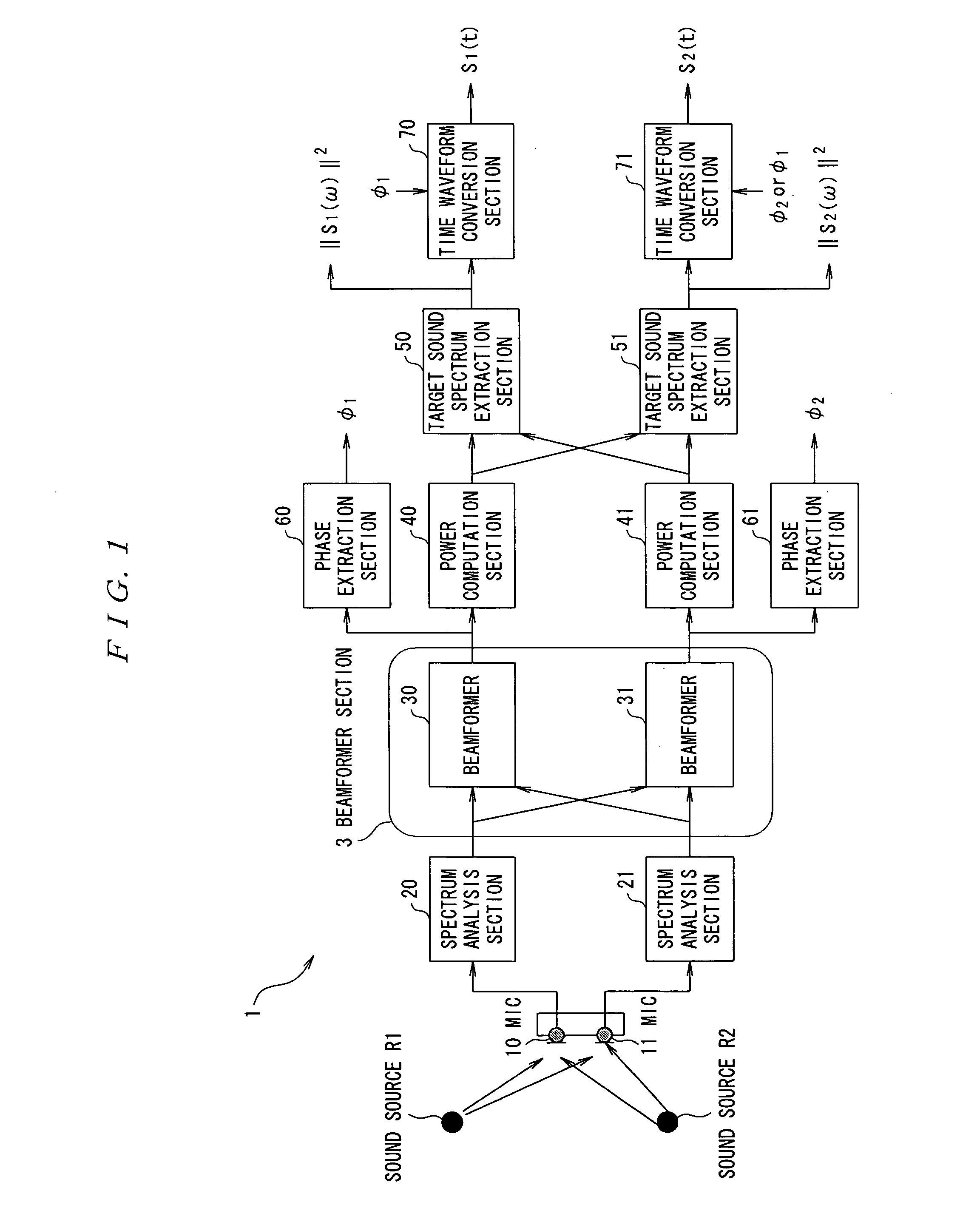
[0094]FIG. 1 is a diagram which shows a basic configuration of a sound source separation system according to the first embodiment of the present invention. This system is comprised of two microphones (hereinafter referred to as MIC) 10, 11 and a sound source separation device 1. This sound source separation device 1 includes a CPU that performs overall control and arithmetic processing, hardware including storage devices a ROM, a RAM, and a hard disk device, and software including a program, data, and the like stored in the storage devices, which are not shown. Function blocks shown in FIG. 1 are implemented by these hardware and software.
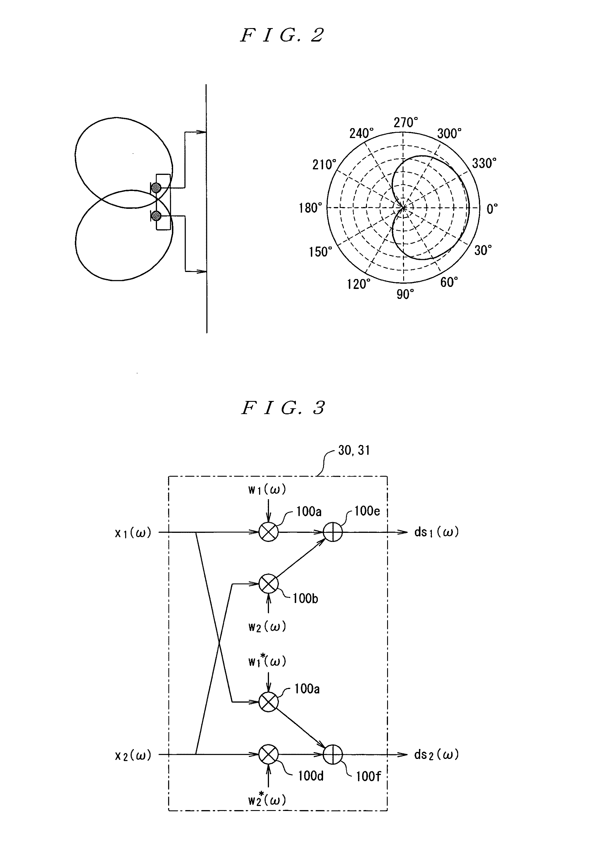
[0095]The two MICs 10 and 11 are non-directional MICs and arranged separately by a few centimeters from each other on a plane. Although the MICs 10 and 11 are basically omnidirectional, unidirectional microphones may be used as shown in FIG. 2. The MICs 10 and 11 receive signals emitted from two sound sources R1 and R2. At this time, these two soun...
second embodiment
[0135]Next, the second embodiment will be described. FIG. 17 shows a configuration of a sound source separation system according to the second embodiment. Although inputs from the MICs 10 and 11 are converted into frequency components at first by the spectrum analysis sections 20 and 21 in the above described first embodiment, in the present embodiment, a directional null is formed in a time domain by beamformers 80 and 81 at first, and generate a signal in which a signal from a specific arrival direction is attenuated by beamformers 80 and 81, and then conversion into frequency components is performed by the spectrum analysis sections 20 and 21. In FIG. 17, those having the same functions as in FIG. 1 are given the same reference numbers. Configurations of the beamformers 80 and 81 are implemented by performing filter processing configured as a form of an FIR filter or the like as shown in FIG. 18. At this time, coefficients of the FIR filter can be obtained by converting the weigh...
third embodiment
[0136]Next, the third embodiment will be described. FIG. 19 and FIG. 20 are diagrams which show configurations of sound source separation systems according to the third embodiment. As described above, the target sound spectrum extraction sections 50 and 51 shown in FIG. 1 and FIG. 17 are implemented as the configuration shown in FIG. 5, and are configured to perform sound source separation processing using an optimum threshold value obtained by experiment. On the other hand, as shown in FIG. 8, it is understood that dri(ω) (i=1, 2) which are outputs of the difference calculation sections 500 and 501 in the target sound spectrum extraction sections 50 and 51 are point-symmetric with respect to the front 0 degree. Therefore, when thresholds are set to “0” in the coefficient conversion sections 501 and 511 in the target sound spectrum extraction sections 50 and 51 by checking only signs in the calculation sections 500 and 501, if it is positive, power spectrum information of a sound so...
PUM
 Abstract
Description
Claims
Application Information
 - R&D
- Intellectual Property
- Life Sciences
- Materials
- Tech Scout
- Unparalleled Data Quality
- Higher Quality Content
- 60% Fewer Hallucinations
Browse by: Latest US Patents, China's latest patents, Technical Efficacy Thesaurus, Application Domain, Technology Topic, Popular Technical Reports.
© 2025 PatSnap. All rights reserved.Legal|Privacy policy|Modern Slavery Act Transparency Statement|Sitemap|About US| Contact US: help@patsnap.com


