

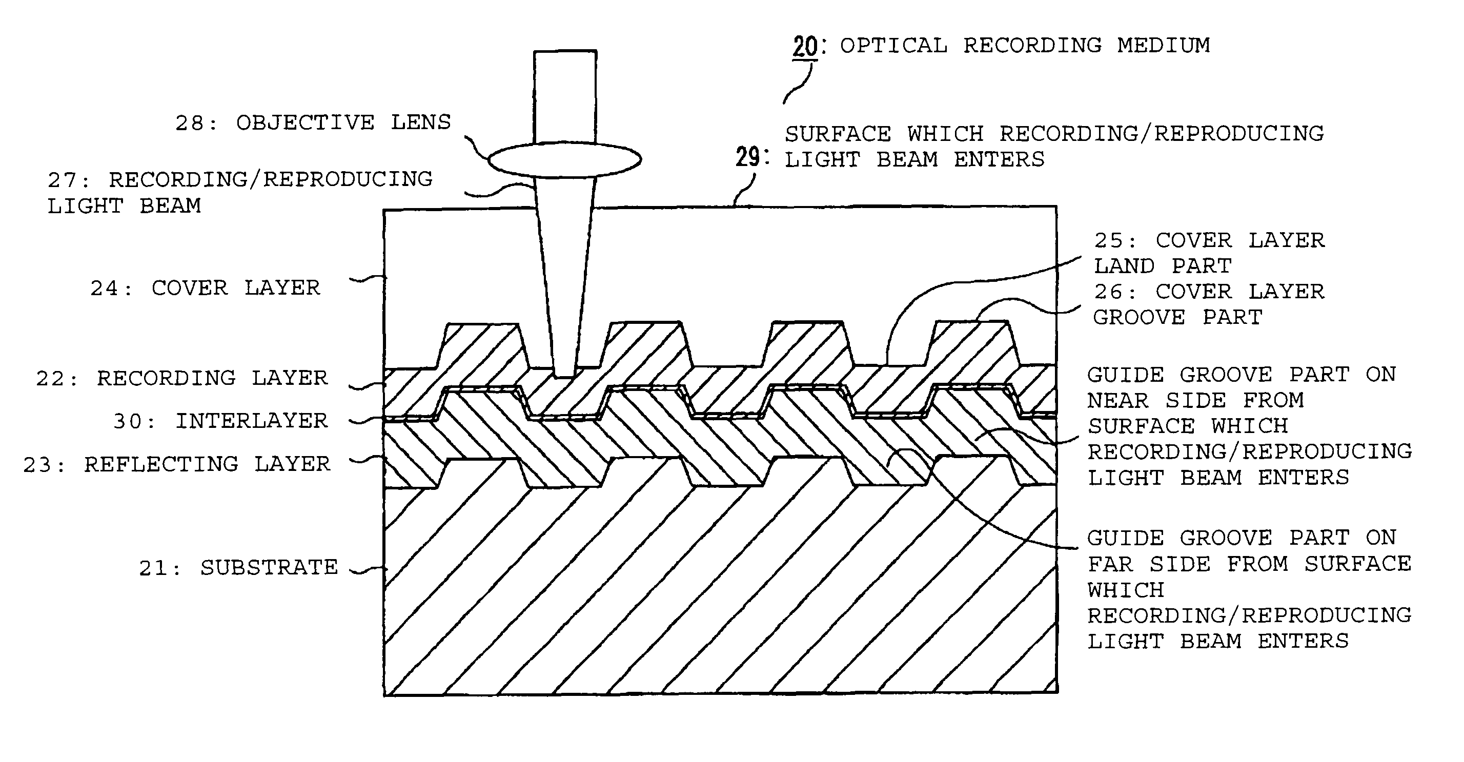
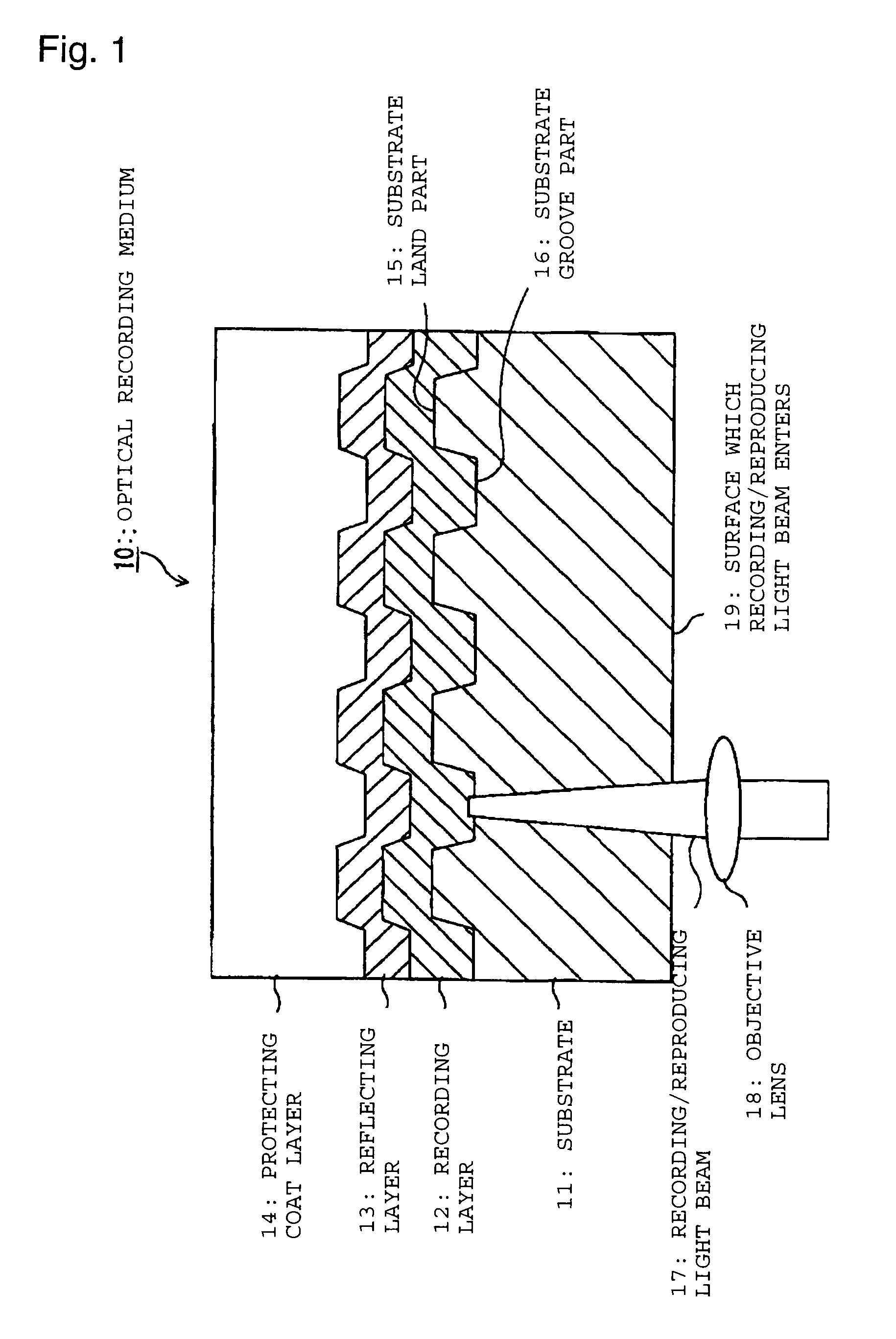
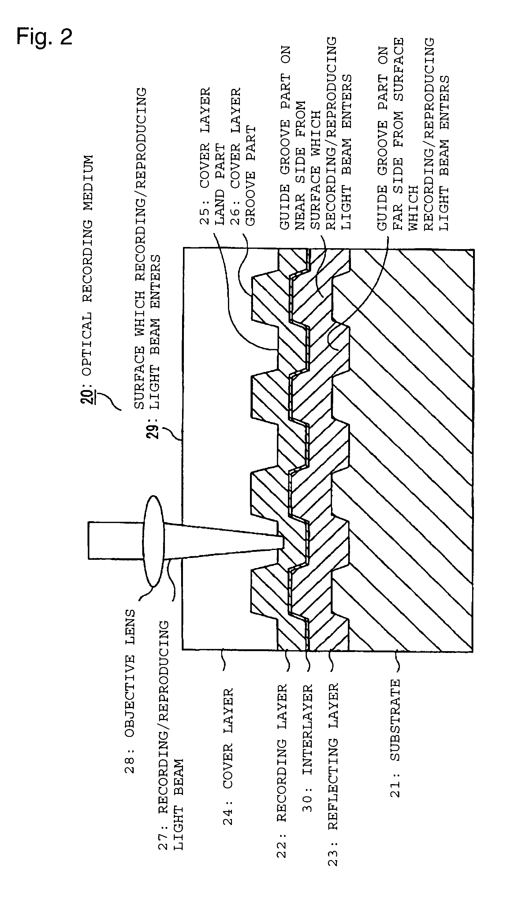
Optical recording medium
a recording medium and optical technology, applied in the field of optical recording mediums, can solve the problems of reducing the pitch of the track, difficult to implement recording in the cover layer groove part, and limiting the density of the recording, and achieve good jitter characteristics
- Summary
- Abstract
- Description
- Claims
- Application Information
AI Technical Summary
Benefits of technology
Problems solved by technology
Method used
Image

Examples
example 1
[0336]A reflecting layer with a thickness of about 65 nm was formed by sputtering of an alloy target with a composition of Ag98.1Nd1.0Cu0.9 (the composition is indicated by atomic %), on a substrate of a polycarbonate resin in which a guide groove with a track pitch of 0.32 μm, a groove width of about 0.18 μm and a groove depth of about 55 nm was formed. An interlayer with a thickness of about 3 nm was formed by sputtering of Ta on the reflecting layer. Furthermore, a dye represented by the below structural formula was dissolved in octafluoropentanol (OFP) and the resulting solution was applied onto the above-mentioned interlayer by a spin-coating method to form a film.
[0337]
[0338]The conditions of the spin-coating method were as follows. Namely, 1.5 g of a solution obtained by dissolving the above dye in a concentration of 0.6% by weight in OFP was dispensed in a ring shape to the vicinity of the center of the disc (obtained by forming the reflecting layer and interlayer on the abo...
example 2
[0341]The following conditions were changed among those in Example 1. Namely, the groove depth of the guide groove formed on the substrate was changed to about 48 nm, the thickness of the reflecting layer was changed to about 70 nm, the material for the interlayer was changed to Nb, and the thickness of the interlayer was changed to about 3 nm. Furthermore, the spin coating of the dye for forming the recording layer was conducted as follows: 1.5 g of a solution obtained by dissolving the above dye in a concentration of 1.2% by weight in OFP was dispensed in a ring shape to the vicinity of the center of a disc (obtained by forming the reflecting layer and interlayer on the above-mentioned substrate), the disc was rotated at 120 rpm for 4 seconds, and then the disc was rotated at 1200 rpm for 3 seconds to spread the dye solution. Thereafter, the disc was rotated at 9200 rpm for 3 seconds to sweep off the dye solution, thereby conducting coating. In addition, ZnS—SiO2 (molar ratio of 6...
example 3
[0342]An optical recording medium was prepared under the same conditions as in Example 2 except that the thickness of the interlayer of Nb was changed to about 5 nm among the conditions in Example 2.
PUM
 Abstract
Description
Claims
Application Information