Accoustically transparent occlusion reduction system and method

a transparent and occlusion reduction technology, applied in the direction of occlusion effect electronic compensation, transducer details, electrical transducers, etc., can solve the problems of increasing the sound pressure within the occluded of partially occluded ear, creating discomfort and/or unnatural sound sensation, and limiting the amplification of hearing aids

Active Publication Date: 2012-02-14
SIVANTOS PTE LTD
View PDF14 Cites 38 Cited by
  • Summary
  • Abstract
  • Description
  • Claims
  • Application Information

AI Technical Summary

Benefits of technology

[0006]It is an object of the present invention to provide an improved occlusion reduction system for applications such as hearing aids, personal sound devices, in ear monitors, communications headsets and hearing protection devices.
[0008]The negative-feedback loop preferably can include a filter that alters the open loop response so that the real component of the response is large and negative at frequencies where the occlusion effect can be typically the greatest. Consequently reducing all signals introduced into the closed loop within this frequency range.

Problems solved by technology

As a result, the occlusion effect creates discomfort and / or an unnatural sound sensation.
This problem is commonly reported to clinicians in the hearing aid industry as it affects a large number of hearing aid wearers (those with mild low-frequency hearing loss).
On the other hand, a sufficiently large vent limits the hearing aid amplification due to oscillations created by positive feedback occurring around the loop defined by an external microphone, amplifier, receiver, and path through the vent back to the external microphone.
The soft tissue in the ear canal is excited by vibration energy propagated by the skull and jaw due to the wearer's voice and this results in an increased sound pressure within the occluded of partially occluded ear relative to an open ear.
However there are a number of practical problems relating to the deep insertion of an earmold, for instance physical discomfort.
While some of the aforementioned patents include methods to alter the response of the electro-acoustic feedback system, none of these patents incorporate methods to compensate for the effect that response alteration within the feedback system has on external signals such as from an external microphone or hearing aid processor.
In addition, the aforementioned patents do not provide a mechanism to prevent the receiver from overloading by sensing the level of signal at the optimum point, being the input to the receiver.

Method used


Image

  • Accoustically transparent occlusion reduction system and method
  • Accoustically transparent occlusion reduction system and method
  • Accoustically transparent occlusion reduction system and method

Examples


Embodiment Construction

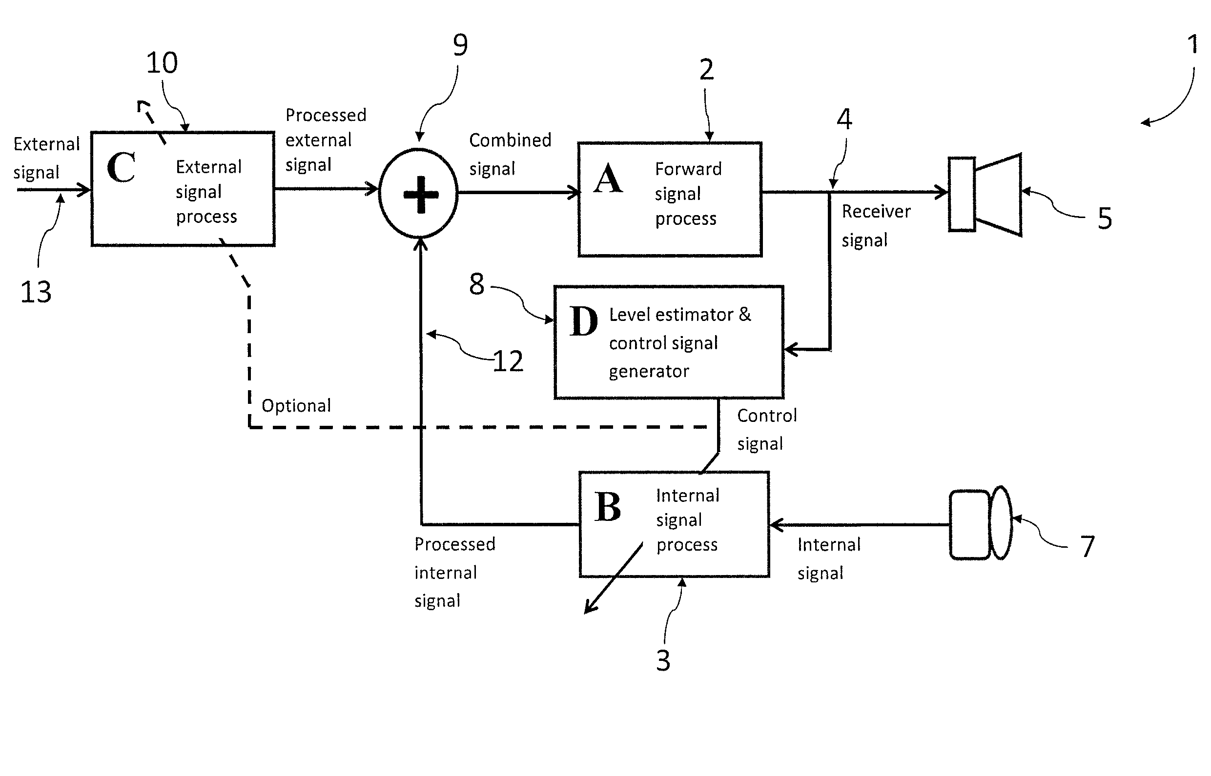
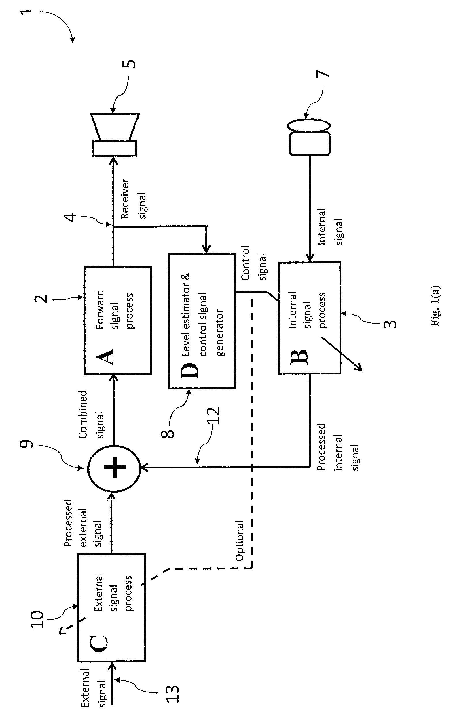
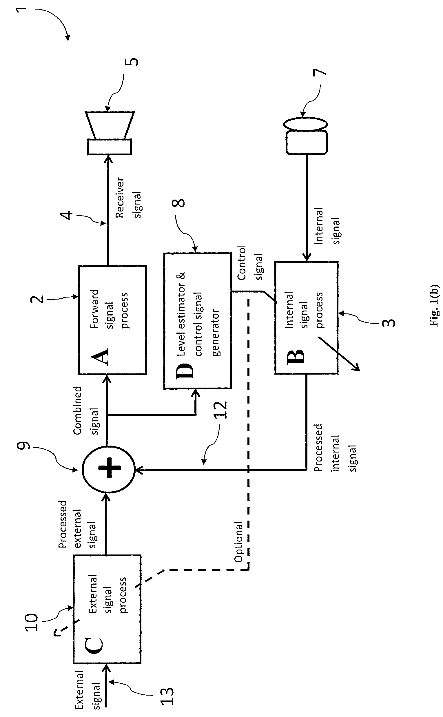
[0029]The preferred embodiment operates to reduce the level of signals generated within an electro-acoustic negative feedback loop, such as signals produced by vibration in the ear canal walls due to bone conduction of a user's voice. The reduction occurs in the low to mid audible frequencies, typically ranging from 80 Hz up to 1 kHz, where the occlusion effect is more predominant and perceptually apparent.

[0030]A negative feedback scheme is provided which combines a processed externally generated signal such as from an external microphone or a sound system with a processed internal signal such as from a microphone located within or closely coupled to the occluded or partially occluded ear. The combined signal after optional further processing is applied to a receiver located within or closely coupled to the occluded or partially occluded ear. The level of the signal to be applied to the receiver is optimally estimated either from the signal applied to the receiver or from the combi...


PUM


Abstract

A system and method that reduces the perceptual effect resulting from ear occlusion include an electro-acoustic feedback network that produces phase canceling sounds in the ear, where a receiver and a microphone are located. A control mechanism controls the response of the feedback network to minimize distortion in the ear while maintaining a desired frequency response for external signals. Devices producing the external signal include hearing aids, personal sound devices, in ear monitors, communications headsets and hearing protectors. The integration of the above with these devices improves a user's perception of their own voice.

Description

FIELD OF THE INVENTION[0001]The present invention relates to an improved occlusion reduction system for applications such as hearing aids, personal sound devices, in ear monitors, communications headsets and hearing protection devices.DESCRIPTION OF BACKGROUND ART[0002]An electro-acoustic negative feedback scheme was originally presented by H. F Olson, in 1961 in U.S. Pat. No. 2,983,790. A more comprehensive implementation was later proposed by Bose et al, in 1982 in U.S. Pat. No. 4,494,074 under the title “Feedback Control”. Using headphones, Bose proposed the idea of an electro-acoustic feedback in the proximity of the ear canal. The concept was later used by Langberg et al, in 1988 in U.S. Pat. No. 4,985,925, describing a system functioning as a bilateral transducer drive with a shunt feedback correction network. Later on in 1991, Langberg et al, in U.S. Pat. No. 5,267,321 entitled “Active Sound Absorption” describes an electro-acoustical feedback system, with the receiver acting...

Claims


Application Information

Patent Timeline
Patent Type & Authority Patents(United States)
IPC IPC(8): H04R25/00H04R3/00
CPCH04R25/502H04R25/505H04R25/407H04R2460/05
Inventor MEJIA, JORGE PATRICIODILLON, HARVEY ALBERTFISHER, MICHAEL JOHN AMIEL
Owner SIVANTOS PTE LTD
Why Eureka
Try Eureka