
Optical scanning and imaging systems based on dual pulsed laser systems

a laser system and scanning laser technology, applied in the field of scanning pulsed laser systems, can solve the problems of excessive data acquisition time, unsatisfactory, and prior dual scanning laser systems have a number of limitations when applied to spectroscopy, and achieve the effect of minimizing the noise of the carrier envelope offset frequency

Active Publication Date: 2012-02-21
IMRA AMERICA
View PDF68 Cites 23 Cited by
  • Summary
  • Abstract
  • Description
  • Claims
  • Application Information

AI Technical Summary

Benefits of technology

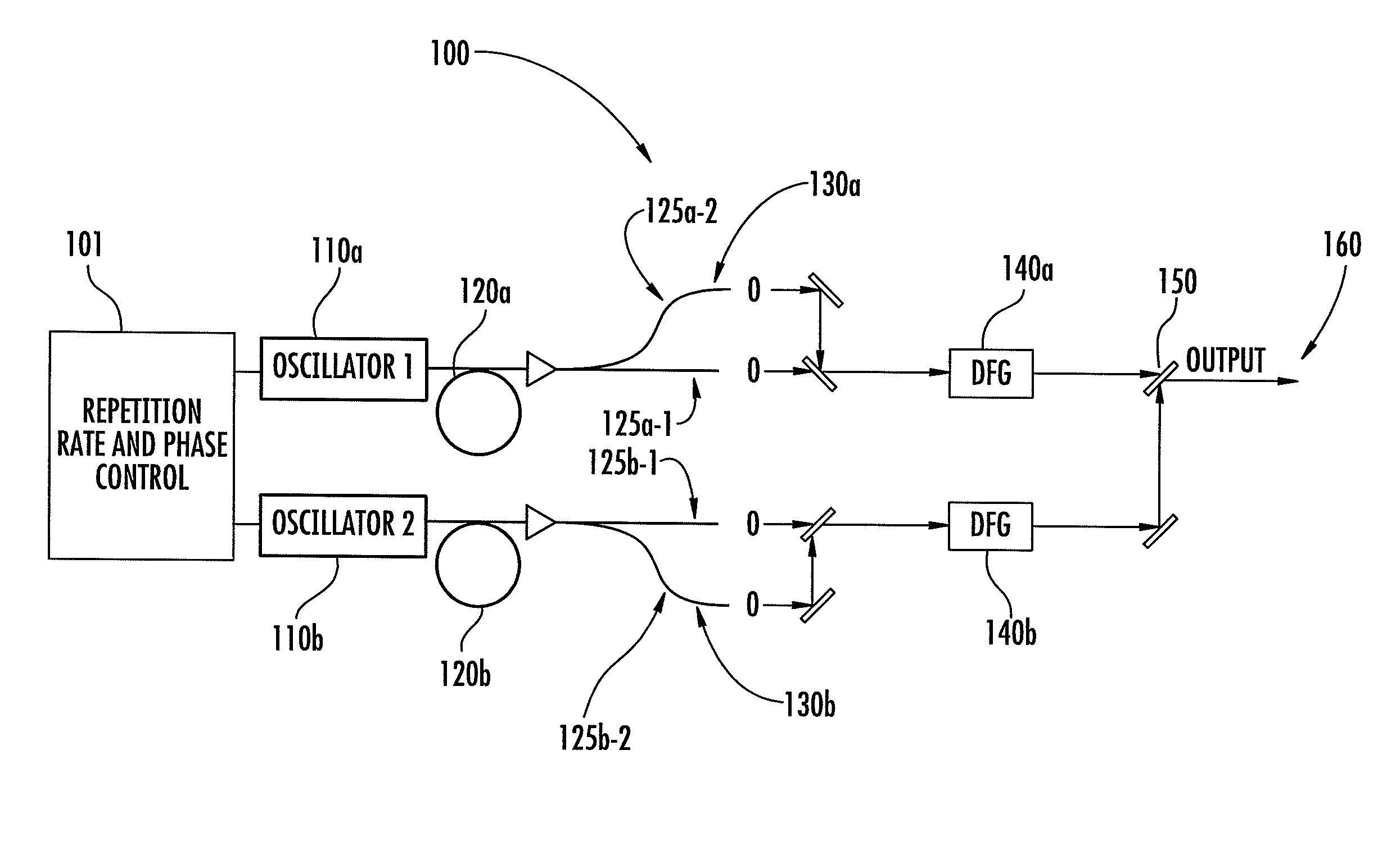
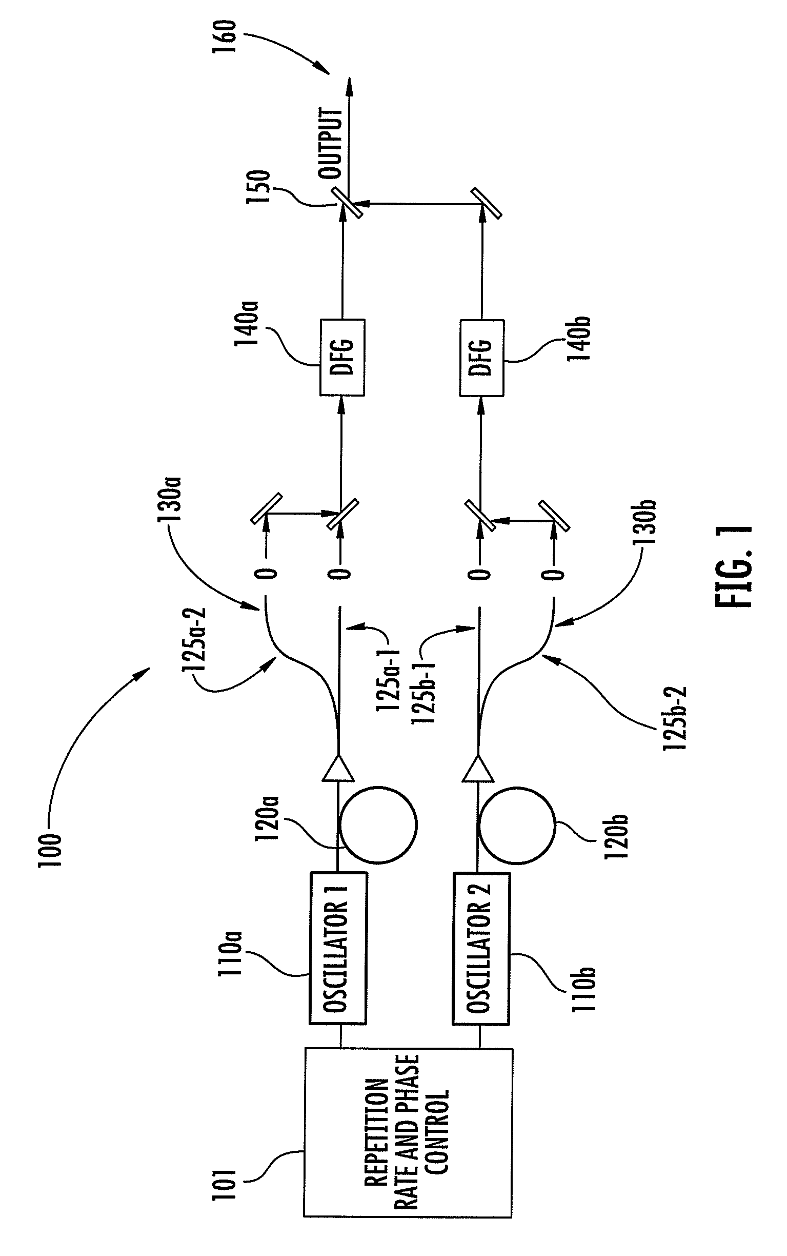
[0013]We further disclose the use of highly nonlinear waveguides in conjunction with coherent supercontinuum generation for generating an optical output from the visible to the mid-infrared spectral region. Difference frequency generation (DFG) produces output in the mid-IR spectral region and simplifies the implementation of FTS. DFG eliminates variations of the carrier envelope offset frequency external to the laser cavity and thus produces an output spectrum comprising true harmonics of the laser repetition rates.
[0016]Nonlinear signal interference in nonlinear frequency broadening elements from overlapping pulses can be eliminated by using separate nonlinear frequency broadening elements for each laser. Alternatively, an optical delay line can be inserted at the output of the CDSL to produce an interference signal only from pulses that do not overlap in any nonlinear optical elements. Electronic gating can further be implemented for optimum signal conditioning.
[0022]The noise of the carrier envelope offset frequencies can be minimized by an appropriate adjustment of the intra-cavity laser dispersion, and the pulse width injected into the supercontinuum fibers.

Problems solved by technology

Note that in this scheme a beat signal at a difference frequency as low as δ is used, which is not ideal, since δ typically has a small value where acoustic noise can corrupt the signal.
Prior dual scanning laser systems have a number of limitations when applied to spectroscopy.
The low repetition rate of implemented laser sources leads to excessively long data acquisition times. and the techniques for signal generation in the near IR to mid-IR spectral range are relatively cumbersome.
Systems implemented with bulky solid-state lasers are not well suited for instrumentation applications and require a large components count.

Method used


Image

  • Optical scanning and imaging systems based on dual pulsed laser systems
  • Optical scanning and imaging systems based on dual pulsed laser systems
  • Optical scanning and imaging systems based on dual pulsed laser systems

Examples


Embodiment Construction

[0038]This description first discusses some aspects of mode-locked lasers and frequency comb generation particularly related to CDSL and applications thereof. Examples of applications of such lasers for IR spectroscopy and THz imaging are included.

[0039]Modelocked lasers with fixed optical frequency spectra comprising a set of equidistant optical frequency lines are typically also referred to as frequency comb lasers. The optical frequency spectrum of a frequency comb laser can be described by S(f)=fceo+mfrep, where m is an integer, fceo is the carrier envelope offset frequency and frep is the repetition rate of the laser. The amplitudes of the individual frequency lines in fact sample the optical envelope spectrum at discrete points fceo+mfrep in optical frequency space.

[0040]Frequency comb lasers were described in U.S. Pat. No. 6,785,303 to Holzwarth et al., where the control of the pump power of a modelocked laser in conjunction with electronic feedback loops is used to stabilize...


PUM


Abstract

The invention relates to scanning pulsed laser systems for optical imaging. Coherent dual scanning laser systems (CDSL) are disclosed and some applications thereof. Various alternatives for implementation are illustrated, including highly integrated configurations. In at least one embodiment a coherent dual scanning laser system (CDSL) includes two passively modelocked fiber oscillators. The oscillators are configured to operate at slightly different repetition rates, such that a difference δfr in repetition rates is small compared to the values fr1 and fr2 of the repetition rates of the oscillators. The CDSL system also includes a non-linear frequency conversion section optically connected to each oscillator. The section includes a non-linear optical element generating a frequency converted spectral output having a spectral bandwidth and a frequency comb comprising harmonics of the oscillator repetition rates. A CDSL may be arranged in an imaging system for one or more of optical imaging, microscopy, micro-spectroscopy and / or THz imaging.

Description

BACKGROUND OF THE INVENTION[0001]1. Field of the Invention[0002]The invention relates to scanning pulsed laser systems for optical imaging.[0003]2. Description of the Related Art[0004]Dual pulsed laser systems comprising two modelocked lasers operating at two slightly different repetition rates f1 and f2, such that δ=|(f1−f2)|<<f1 and δ=|(f1−f2)|<<f2, are useful instruments for the rapid interrogation of optical response functions of widely varying electronic and opto-electronic devices such as photoconductive switches and integrated circuits. Additionally the use of dual pulsed laser systems has also been suggested for THz imaging as disclosed in U.S. Pat. No. 5,778,016 and U.S. Pat. No. 6,396,856 to Sucha et al.[0005]The use of dual modelocked lasers can be replaced for probing the optical response functions by implementing dual electronic circuit systems, as has been suggested in U.S. Pat. No. 5,748,309 by van der Weide. The approach has some benefit for the interroga...

Claims


Application Information

Patent Timeline
Patent Type & Authority Patents(United States)
IPC IPC(8): G01B9/02H01S3/13G01J3/45
CPCG01N21/31H01S3/10046H01S3/2383G01B9/02001H01S3/13G02B6/02304H01S3/0675H01S3/06754H01S3/08054H01S3/1067H01S3/1068H01S3/1115H01S3/1307H01S3/1392H01S3/1394G01N2021/317
Inventor FERMANN, MARTIN E.HARTL, INGMAR
Owner IMRA AMERICA
Learn More