
Optical device for analyzing a scattering medium held by a support

a technology of optical devices and scattering mediums, applied in the field of optical devices for analyzing scattering mediums held by supports, can solve the problems of forming artifacts, affecting the analysis of scattering mediums, and bulky optical devices

Active Publication Date: 2012-02-21
COMMISSARIAT A LENERGIE ATOMIQUE ET AUX ENERGIES ALTERNATIVES
View PDF11 Cites 19 Cited by
  • Summary
  • Abstract
  • Description
  • Claims
  • Application Information

AI Technical Summary

Benefits of technology

[0013]The present invention aims at an optical device for analyzing a scattering medium held by a support comprising a light source and a sensor, the light source being distant from the medium to be analyzed, the support enabling to decrease, or even to suppress, the forming of artifacts on the images acquired by the sensor.
[0014]Another feature of the support is that it can be made in a simple way.

Problems solved by technology

However, such optical devices are generally bulky since the accessible accuracy of the distribution of the optical properties depends on the number of independent measurements that may be performed, that is, on the number of optical fibers used.
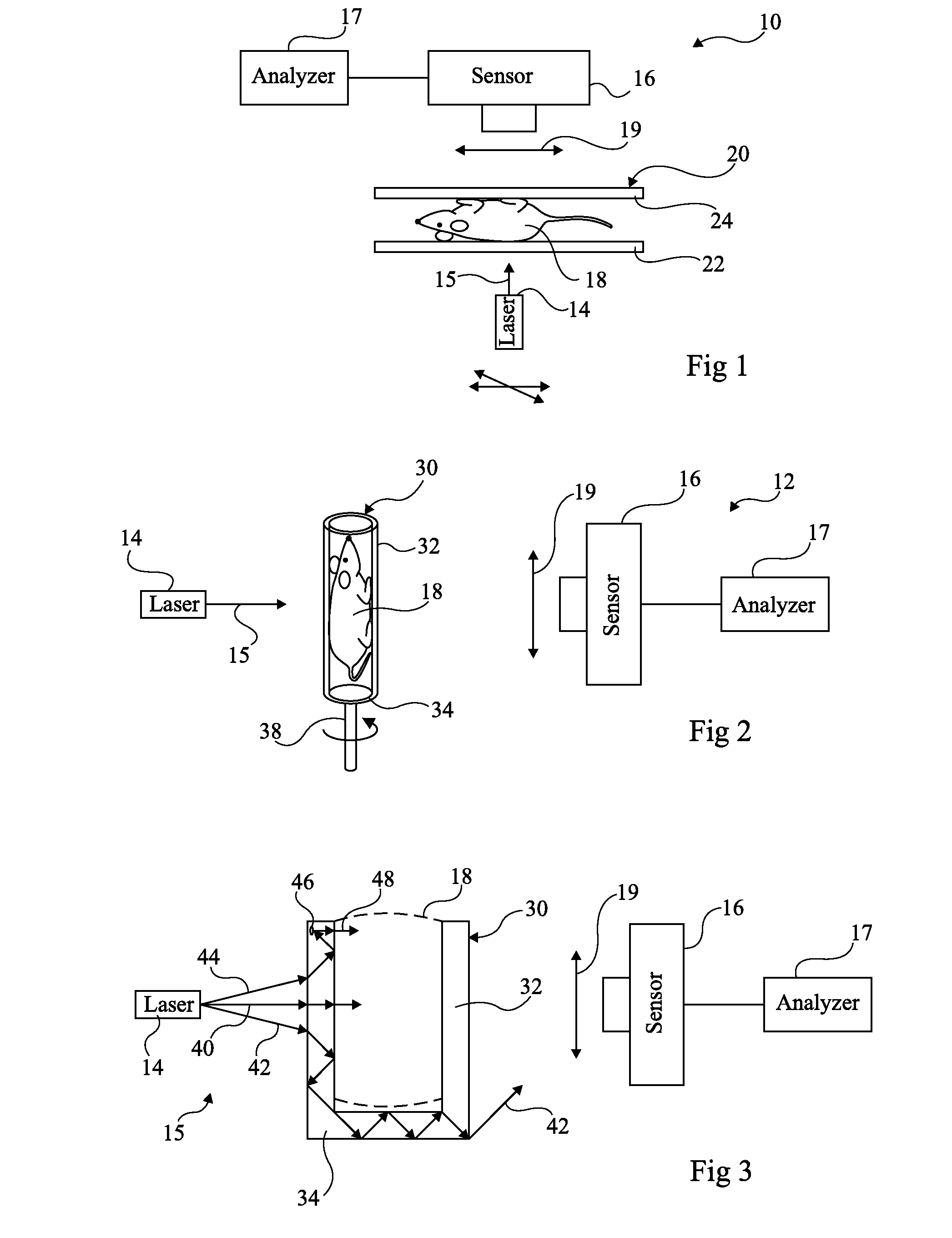
However, the use of such supports may result in the forming of artifacts on the images provided by sensor 16.
Such artifacts may disturb, or even hinder the analysis of scattering medium 18.

Method used


Image

  • Optical device for analyzing a scattering medium held by a support
  • Optical device for analyzing a scattering medium held by a support
  • Optical device for analyzing a scattering medium held by a support

Examples


first embodiment

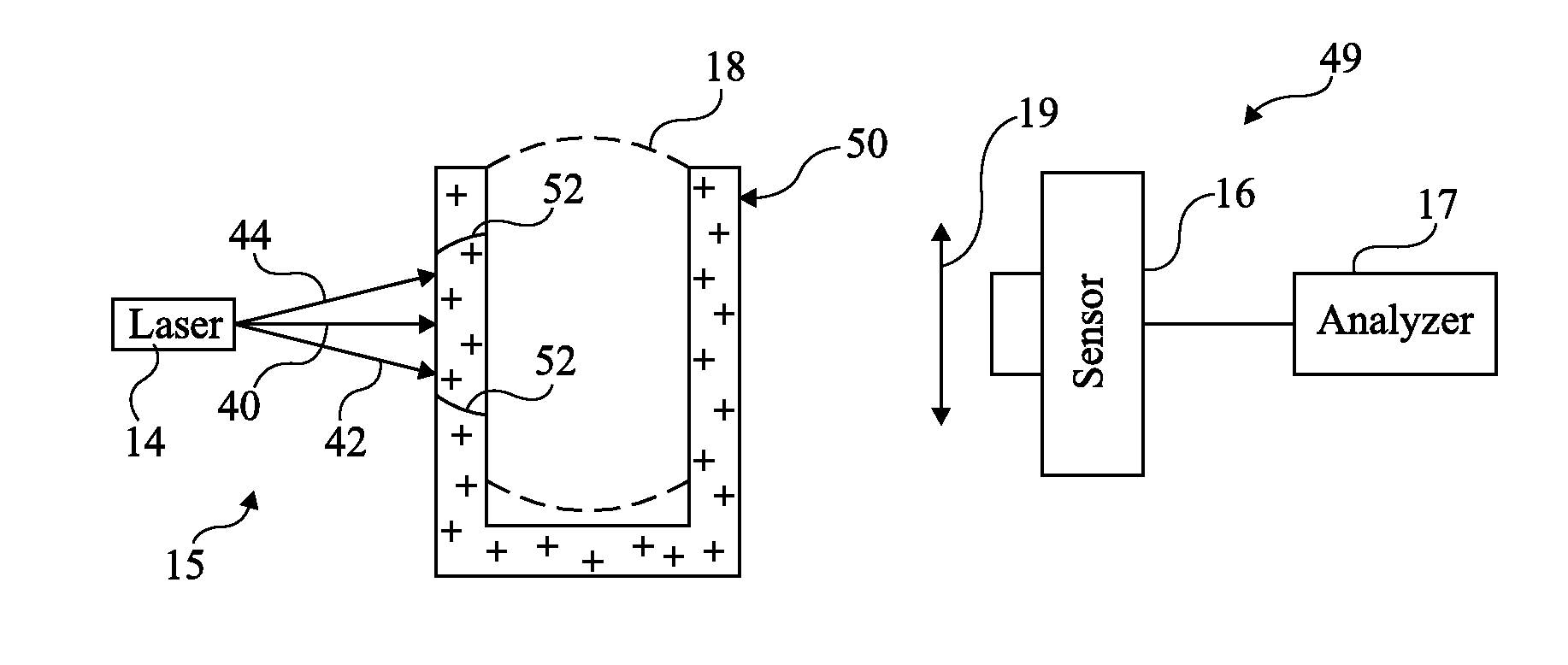
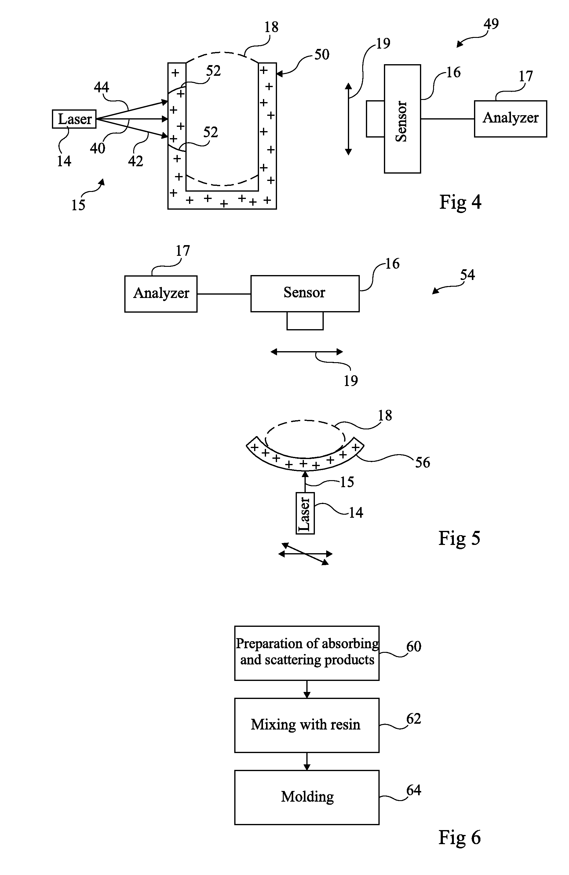
[0037]FIG. 4 shows an optical device 49 according to the present invention. Optical device 49 comprises the same elements as device 12 shown in FIG. 3, except that it has a support 50 formed of a scattering material. Lines 52 schematically designate the diffusion region of incident light beam 15 reaching support 50. In the embodiment shown in FIG. 3, support 50 is tubular. However, support 50 may have another shape and, for example, comprise two parallel plates, in the same way as for optical device 10 shown in FIG. 1.

[0038]The support can also be applied against at least a part of a surface of a diffusing medium to be analyzed without necessarily containing or supporting the diffusing object to be analyzed in a given position. The aim is then to provide a diffusion of the incident light produced by a light source placed at a distance of the support, obtaining the advantages disclosed hereinafter. In such an arrangement, the support can be considered as a diffusing interface medium....

second embodiment

[0039]FIG. 5 shows an optical device 54 according to the present invention. Optical device 56 comprises the same elements as device 10 shown in FIG. 3, except that it comprises a support 56 formed of a scattering material and having the shape of a cradle in which scattering medium 18 to be analyzed is placed. In the present embodiment, the shape of support 56 is advantageously adapted to scattering medium 18. This enables to decrease the possibilities of motion of the scattering medium during the analysis, in particular when the scattering medium is an animal or a human being.

[0040]The support being itself a scattering object, it forms with the scattering medium to be analyzed a scattering system having a precisely-known external surface, since it corresponds to the external surface of the support. Since this surface may correspond to a simple geometric shape, the resolution of the light propagation equations in scattering media can be simplified.

[0041]Another advantage of such a su...


PUM


Abstract

An optical device intended for the analysis of a scattering medium, including at least one light source distant from the scattering medium and capable of providing an incident light beam intended to illuminate the scattering medium; at least one sensor capable of detecting a radiation emitted by the scattering medium; a support of the scattering medium at least partially non-absorbing for the incident light beam and the scattered radiation. All or part of the support is formed of a scattering material having a decreased scattering coefficient greater than 0.1 cm−1 and smaller than 700 cm−1.

Description

BACKGROUND OF THE INVENTION[0001]1. Field of the Invention[0002]The present invention relates to an optical device for analyzing a scattering medium held by a support.[0003]2. Discussion of the Related Art[0004]A subject area of optical imaging relates to the analysis of a scattering medium, for example, the analysis of biological tissues.[0005]Generally, the scattering medium is submitted to an incident light beam. For certain applications, for example, in optical diffusion tomography, the wavelength of the incident beam is in the visible spectrum, conventionally in the red or in the near infrared, which corresponds to the wavelength range where the absorption of the biological tissues is minimum. The incident light beam scatters into the scattering medium and the scattered light radiation which escapes from the scattering medium is detected by a sensor, for example, a camera. The images provided by the sensor are analyzed to determined the optical properties of the scattering medi...

Claims


Application Information

Patent Timeline
Patent Type & Authority Patents(United States)
IPC IPC(8): G01B11/30G01B11/24
CPCA61B5/0073G01N21/0303G01N21/6456G01N21/4795A61B2503/40
Inventor DA SILVA, ANABELARIZO, PHILIPPEBERGER, MICHELGUYON, LAURENT
Owner COMMISSARIAT A LENERGIE ATOMIQUE ET AUX ENERGIES ALTERNATIVES
Learn More