Optical material and optical element, diffraction optical element, and stacked type diffraction optical element molded thereof

a technology of optical elements and optical materials, applied in the direction of optics, diffraction gratings, instruments, etc., can solve the problems of increasing apparent particle size, difficult to correct chromatic aberration sufficiently, and increasing the agglomeration of fine particles of metal oxides, so as to reduce optical scattering and low dispersion characteristics

Inactive Publication Date: 2012-02-21
CANON KK
View PDF64 Cites 25 Cited by
  • Summary
  • Abstract
  • Description
  • Claims
  • Application Information

AI Technical Summary

Benefits of technology

[0015]An object of the present invention is to provide an optical material which causes reduced optical scattering, the optical material having low dispersion characteristics and secondary dispersion characteristics equivalent to those of a compound in which fine particles of a conductive metal oxide such as ITO are dispersed in an organic resin.

Problems solved by technology

However, it is sometimes difficult to correct chromatic aberration sufficiently if there are limits on the configuration or number of lenses or on available glass materials.
At this time, diffracted lights of orders other than a designed order are focused on locations different from light of the designed order, causing flare.
However, with a compound material of fine particles and resin, optical scattering occurs at interfaces between the fine particles and resin.
However, agglomeration of fine particles of metal oxides increases with decreases in the particle size due to van der Waals forces.
This increases apparent particle size, resulting in intense optical scattering.
However, manufacture of fine particles of metal oxides is very demanding.
Slight differences in manufacturing conditions can cause oxygen deficiency in the metal oxides and affect the degree of crystallinity.
These changes in turn affect the shape and physical properties of the fine particles, making it very difficult to keep the particle size and physical properties of the fine particles uniform.

Method used


Image

  • Optical material and optical element, diffraction optical element, and stacked type diffraction optical element molded thereof
  • Optical material and optical element, diffraction optical element, and stacked type diffraction optical element molded thereof
  • Optical material and optical element, diffraction optical element, and stacked type diffraction optical element molded thereof

Examples


example 1

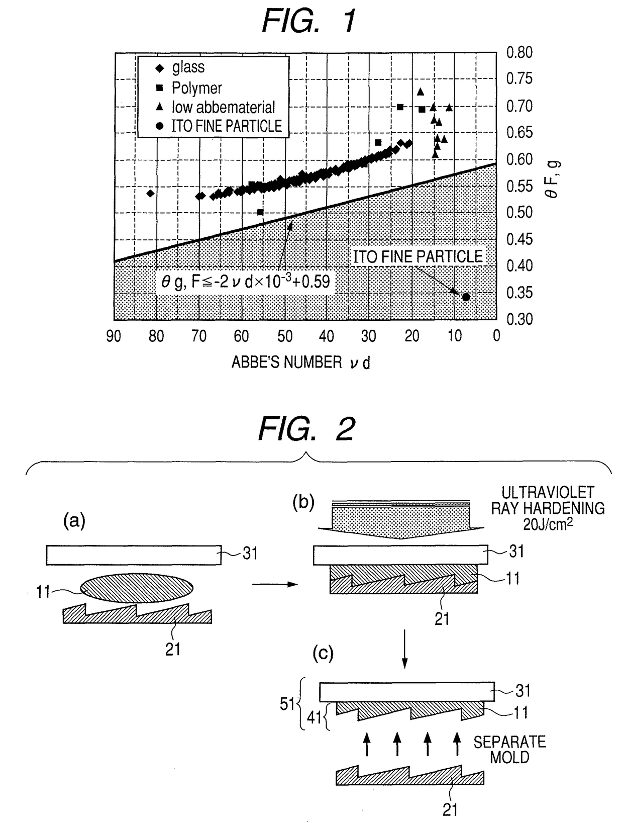
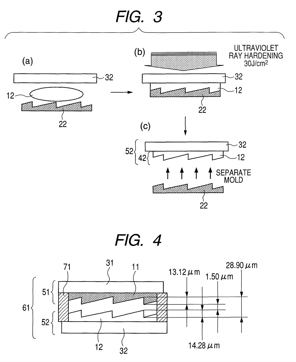
[0065]A configuration and fabrication method of a stacked type diffraction optical element according to example 1 will be described with reference to (a), (b) and (c) of FIG. 2, FIGS. 3 and 4. First, 10.00 g of 1-vinyl-2-pyrrolidone (whose refractive index is 1.523) and 0.31 g of 1-hydroxycyclohexylphenylketone serving as an optical initiator were added to a 45.00 g of a water solution containing 1.30 wt % of colloidally dispersed fine particles of a conductive polymer, namely PEDOT / PSS (manufactured by Aldrich Co.; product No.: 48309-5 & 56059-6; average diameter: 80 nm; refractive index: 1.529 (listed value)). The mixture was stirred using a stirrer to facilitate dispersion and dissolution. Subsequently, the solvent was removed under reduced pressure, and thus an optical material 11 was prepared.

[0066]Next, as illustrated in (a) of FIG. 2, the optical material 11 was supplied to a die 21 formed into a shape of a diffraction grating for this example. Then, as illustrated in (b) of ...

example 2

[0071]An optical material 13 was prepared using the same method as example 1 except that the amount of the water solution with a colloidal dispersion was 65.00 g.

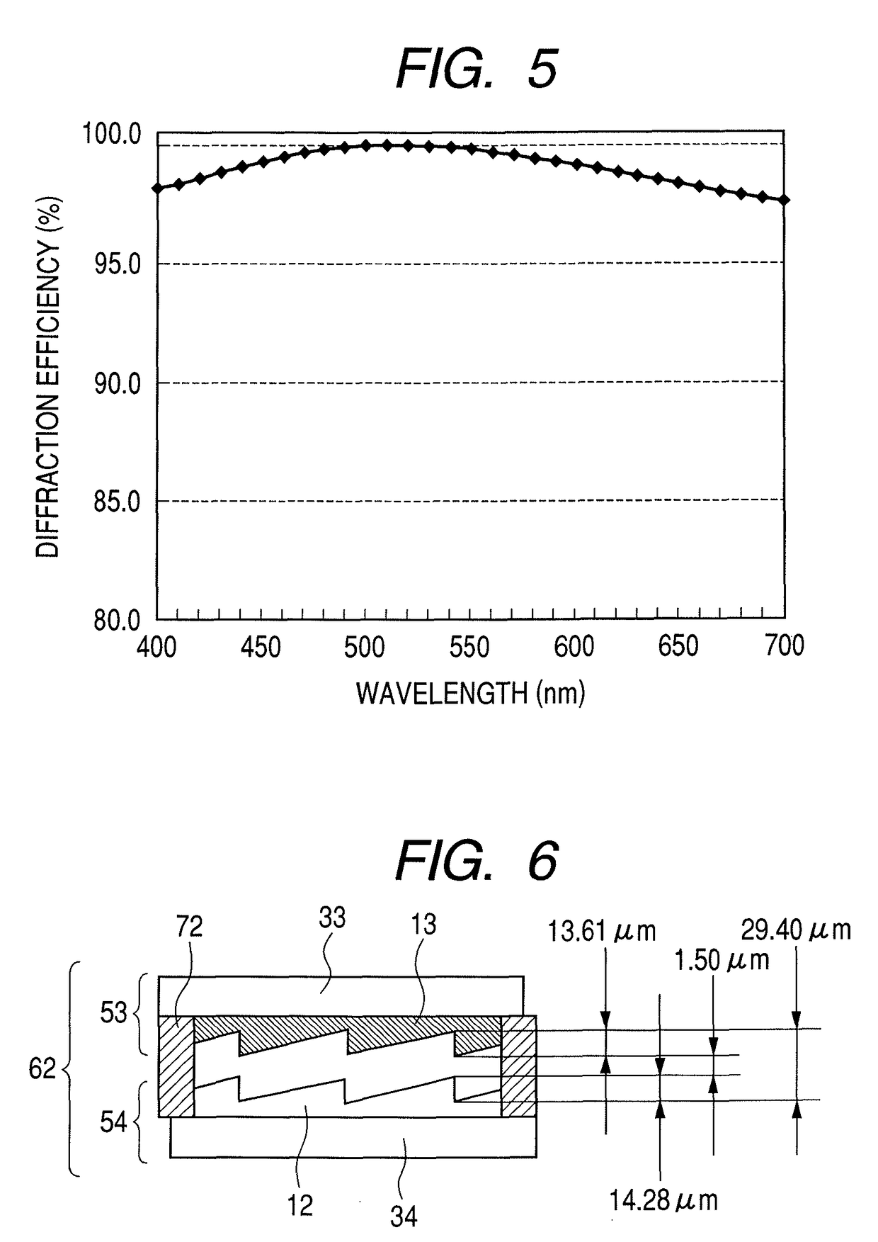
[0072]Also, using a die formed into a shape of a diffraction grating for this example and a flat glass plate 33, a diffraction optical element 53 was fabricated by the same molding method as example 1. Optical characteristics of the optical material 13 were as follows: nd=1.5249; νd=22.29; θg,F=0.422. The optical characteristics satisfy θg,F≦−2νd×10−3+0.59 and θg,F≦0.45.

[0073]On the other hand, to fabricate another optical element, a diffraction optical element 54 was fabricated using a die formed into a shape of a diffraction grating for this example and a flat glass plate 34. The optical material 12 used was the same as in example 1 and optical characteristics of the optical material 12 were as follows: nd=1.5228 and νd=51.42.

[0074]Next, anti-reflection films were formed on diffraction planes of the diffraction optical el...

example 3

[0098]This example concerns a multi-layered diffraction optical element which has a configuration shown in FIG. 12. Details of the example will be described with reference to (a), (b) and (c) of FIG. 13 and (a), (b) and (c) of FIG. 14. FIG. 12 is a sectional view illustrating an example of a double-layered diffraction optical element 65. In FIG. 12, the double-layered diffraction optical element 65 includes a glass substrate 39, first layer 81 and second layer 82 stacked on the first layer 81 so as not to form a gap between the first layer 81 and the second layer 82. The second layer 82 is made of an optical material which satisfies the condition θg,F≦−2νd×10−3+0.59 shown in examples 1 and 2. The first layer 81 is made of an optical material whose Abbe's number is larger than the Abbe's number of the optical material of the second layer 82. And the first layer 81 is made of an optical material whose refractive index is larger than the refractive index of the optical material of the ...


PUM

PropertyMeasurementUnit
average diameteraaaaaaaaaa
diameteraaaaaaaaaa
diameteraaaaaaaaaa

Abstract

Use of an organic optical material whose Abbe's number (νd) and secondary dispersion (θg,F) satisfy the relationship θg,F≦−2νd×10−3+0.59 provides an optical material which causes reduced optical scattering, the optical material having excellent optical scattering characteristics and secondary dispersion characteristics equivalent to those of a compound in which fine particles of conductive metal oxides such as ITO are dispersed in an organic resin.

Description

BACKGROUND OF THE INVENTION[0001]1. Field of the Invention[0002]The present invention relates to an optical material and optical element, diffraction optical element, and stacked type diffraction optical element molded of the optical material.[0003]2. Description of the Related Art[0004]Conventionally, refraction optical systems which use refraction of light to reduce chromatic aberration do so by using a combination of lenses made of glass material with different dispersion characteristics. For example, in a telescope, chromatic aberration which occurs on an axis of an object lens is corrected using a combination of positive lenses made of high-dispersion glass material and negative lenses made of low-dispersion glass material. However, it is sometimes difficult to correct chromatic aberration sufficiently if there are limits on the configuration or number of lenses or on available glass materials.[0005]A. D. Kathman and S. K. Pitalo disclose in “Binary Optics in Lens Design.” Inte...

Claims


Application Information

Patent Timeline
Patent Type & Authority Patents(United States)
IPC IPC(8): G02B5/18
CPCG02B1/04G02B5/1814G02B5/1871G02B27/0037G02B27/0056G02B27/4211G02B27/4277G02B27/4288
Inventor IWASA, HIDEFUMI
Owner CANON KK
Why Eureka
Try Eureka