Pivoting fan nozzle nacelle

a technology of fan nozzle and nacelle, which is applied in the direction of machines/engines, sustainable transportation, climate sustainability, etc., can solve the problems of large increase in the throat area of the fan duct, and achieve the effect of convenient outward high thrust power setting, and convenient pivoting of the fan nozzl

Active Publication Date: 2012-03-06
THE BOEING CO
View PDF88 Cites 28 Cited by
  • Summary
  • Abstract
  • Description
  • Claims
  • Application Information

AI Technical Summary

Benefits of technology

[0016]Although the nozzle system may include a pair of the fan nozzles mounted on opposite sides of the gas turbine engine, the nozzle system is described below in the context of one of the fan nozzles wherein the fan nozzle may be pivoted from a stowed position to a deployed position, and vice versa, about a pivot axis. In one embodiment, the pivot axis may be oriented transversely relative to a longitudinal axis (i.e., engine centerline) of the gas turbine engine. The nozzle system facilitates pivoting of the fan nozzle between stowed and deployed positions. However, in a further embodiment, the fan nozzle may be selectively pivotable to at least one of a plurality of predetermined positions between the stowed and deployed positions.
[0017]In this regard, the nozzle system as disclosed herein provides an ability to tailor the fan duct nozzle throat area to a variety of different engine operating conditions and / or to a variety of different flight conditions. For example, the nozzle system may facilitate outward pivoting of the fan nozzle to provide a larger fan duct nozzle throat area for high thrust power settings and / or for reduced exhaust noise as may be desirable during takeoff. Conversely, the fan nozzle may be pivoted inwardly to the stowed position in order to provide a relatively smaller fan duct nozzle throat area as may be desirable for lower cruise thrust power settings. In this regard, the nozzle system provides a mechanism for achieving a desired fan duct nozzle throat area by pivoting the fan nozzle to a desired position that provides an optimal fan duct nozzle throat area.
[0018]The technical effects of the disclosed embodiments allow for selective positioning of the fan nozzle in order to achieve a variety of different fan duct nozzle throat areas for a high bypass turbofan gas turbine engine. The disclosed embodiments may be implemented on a variety of alternative gas turbine engine configurations and are not limited solely to high bypass turbofan engines. In addition, the nozzle system as disclosed herein results in a relatively large increase in fan duct nozzle throat area for the amount of movement required of the fan nozzle as compared to prior art fan nozzle configurations which are purely axially translating.
[0019]In this regard, the outwardly pivoting fan nozzle as disclosed herein may provide two (2) to three (3) times the increase in fan duct nozzle throat area as compared to purely axially-translating fan nozzles. Even further, the nozzle system as disclosed herein facilitates an increase in fan duct nozzle throat area which may be unachievable by purely aft-translating fan nozzles due to clearance problems with structure mounted behind the engine such as control surfaces (e.g., flaps) mounted on a trailing edge of a wing.
[0020]The nozzle system as disclosed herein may be configured to allow for pivoting motion of the fan nozzle to the deployed position wherein the throat area of the fan nozzle is at a maximum (e.g., to the deployed position) as may be desirable for high thrust settings of the engine during takeoff but where noise suppression is also desired. Likewise, the nozzle system may facilitate pivoting of the fan nozzle to an optimal position (e.g., to the stowed position) for lower engine thrust settings such as during cruise flight where noise suppression is not required but where nozzle efficiency dictates a reduced fan duct nozzle throat area.
[0021]The nozzle system preferably facilitates axially aft movement of the fan nozzle as may be required for thrust reversal actuation purposes. In this regard, the fan nozzle, in one embodiment, may be pivotable between the stowed and deployed positions when the translating sleeve (i.e., fan nozzle) is moved axially aft during thrust reverser actuation or when the translating sleeve is moved axially forward during thrust reverser retraction. Even further, the translating sleeve is configured to be axially translatable in forward or aft directions regardless of whether the fan nozzle is in the deployed or retracted position or in an intermediate position. The fan nozzle may be configured such that axially aft movement thereof may occur non-contemporaneously with inward or outward pivoting of the fan nozzle.

Problems solved by technology

In addition, the nozzle system as disclosed herein results in a relatively large increase in fan duct nozzle throat area for the amount of movement required of the fan nozzle as compared to prior art fan nozzle configurations which are purely axially translating.

Method used


Image

  • Pivoting fan nozzle nacelle
  • Pivoting fan nozzle nacelle
  • Pivoting fan nozzle nacelle

Examples


Embodiment Construction

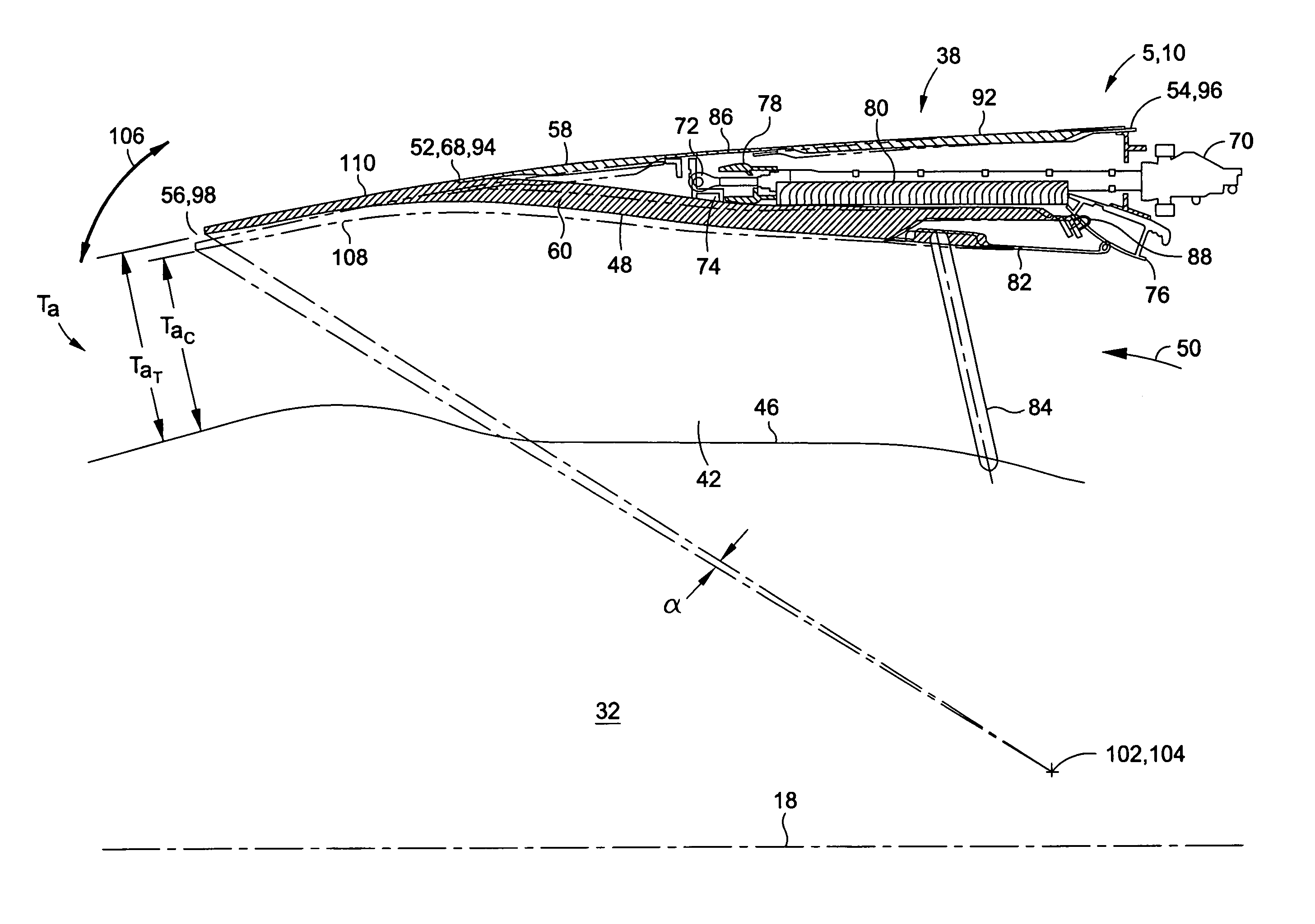
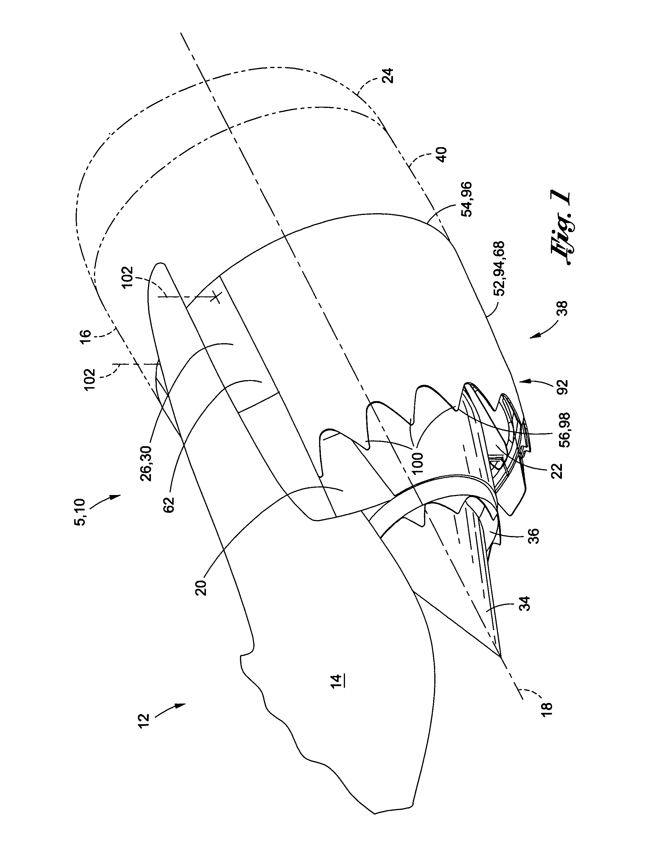
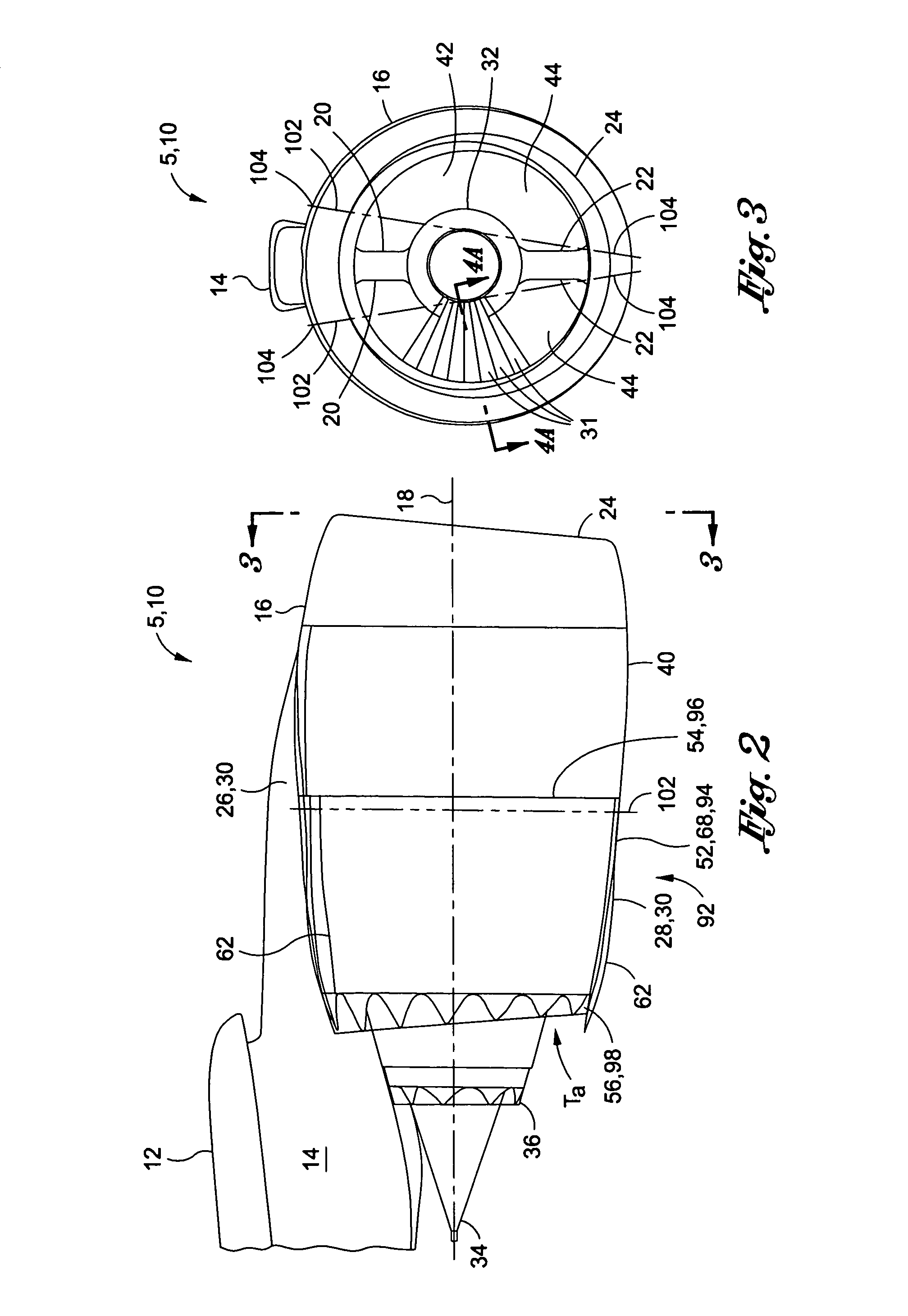
[0038]Referring now to the drawings wherein the showings are for purposes of illustrating preferred and various embodiments of the disclosure only and not for purposes of limiting the same, shown in FIG. 1 is a high bypass turbofan gas turbine engine propulsion system 10 comprising a gas turbine engine 5 housed in a nacelle 16 incorporating a variable area nozzle system 92 as disclosed herein. In a broad sense, the nozzle system 92 may include a pair of fan nozzles 94 mounted on opposing sides of the gas turbine engine 5. Although the nozzle system 92 preferably includes a pair of the fan nozzles 94 as illustrated in the Figures, the disclosed embodiments are described below in the context of a single one of the fan nozzles 94 wherein the described features are applicable to each one of the fan nozzles 94 of the pair. In this regard, the fan nozzle 94 is configured to pivot about a pivot axis 102. The pivot axis 102 is preferably oriented transversely relative to a longitudinal axis...


PUM


Abstract

A variable area nozzle system for a gas turbine engine includes a fan duct inner wall, a fan duct outer wall disposed in radially spaced relation to the fan duct inner wall, and a fan nozzle. The fan nozzle defines at least a portion of the fan duct outer wall and includes a nozzle aft edge. The fan duct inner wall and the nozzle aft edge collectively define a fan duct nozzle throat area. The fan nozzle is configured to pivot about a pivot axis that may be oriented transversely relative to a longitudinal axis of the gas turbine engine. The fan nozzle may be pivoted from a stowed position to a deployed position in order to vary the fan duct nozzle throat area.

Description

CROSS-REFERENCE TO RELATED APPLICATIONS[0001](Not Applicable)STATEMENT RE: FEDERALLY SPONSORED RESEARCH / DEVELOPMENT[0002](Not Applicable)FIELD[0003]The present disclosure relates generally to gas turbine engines and, more particularly, to an engine nacelle having a variable area fan nozzle.BACKGROUND[0004]Aircraft noise pollution is a significant environmental problem for communities near airports. Jet engine exhaust accounts for a majority of the noise produced by engine-powered aircraft during takeoff. Because it occurs at a relatively low frequency, jet engine exhaust noise is unfortunately not effectively damped by the atmosphere alone. The prior art includes several attempts at reducing jet engine exhaust noise. Such attempts are directed at altering the flow characteristics of the engine exhaust which can be comprised of several components.[0005]Bypass turbofan engines typically produce two exhaust stream components. A first component stream is referred to as the primary exhau...

Claims


Application Information

Patent Timeline
Patent Type & Authority Patents(United States)
IPC IPC(8): F02K3/02
CPCF02K1/1207F02K1/72F02K3/04F02K3/06Y02T50/671Y02T50/60
Inventor HOWE, MARK E.
Owner THE BOEING CO
Why Eureka
Try Eureka