Gas homogenization system

a gas homogenization system and gas technology, applied in the direction of ether preparation, process and machine control, filtration separation, etc., can solve the problems of insufficient consideration of prior systems and processes, less desirable disposal of waste materials by incineration, and deviation in gas characteristics, etc., to achieve the effect of improving engine operation and reducing the number of cylinders

Inactive Publication Date: 2012-03-06
PLASCO ENERGY GROUP INC
View PDF120 Cites 23 Cited by
  • Summary
  • Abstract
  • Description
  • Claims
  • Application Information

AI Technical Summary

Benefits of technology

[0023]This invention provides a gas homogenization system for homogenizing the chemical composition of an input gas and adjusting other characteristics such as flow rate, pressure, and temperature of the gas, thereby creating a regulated gas to meet downstream requirements. This system enables a continual and steady stream of gas of defined characteristics to be delivered to downstream applications, for example, a gas turbine, engine or other suitable applications.

Problems solved by technology

It is becoming less desirable to dispose of waste material by incineration because of the extreme waste of fuel in the heating process and the further waste of disposing, as a residual waste, material that can be converted into a useful syngas and solid material.
The gas produced during the gasification of carbonaceous feedstock is usually very hot but may contain small amounts of unwanted compounds and requires further treatment to convert it into a useable product.
Prior systems and processes have not adequately addressed the problems that must be dealt with on a continuously changing basis.
These machines are designed to function within a very strict range of characteristics and are often very sensitive to changes in certain gas characteristics.
In addition to affecting the efficiency of engine operation, a deviation in the gas characteristics may even have a negative effect on engine operation.
For example, changes in the gas characteristics can affect the emissions, efficiency, knock and combustion stability, as well as increase the maintenance requirements of the engine.

Method used


Image

  • Gas homogenization system
  • Gas homogenization system
  • Gas homogenization system

Examples


example 1

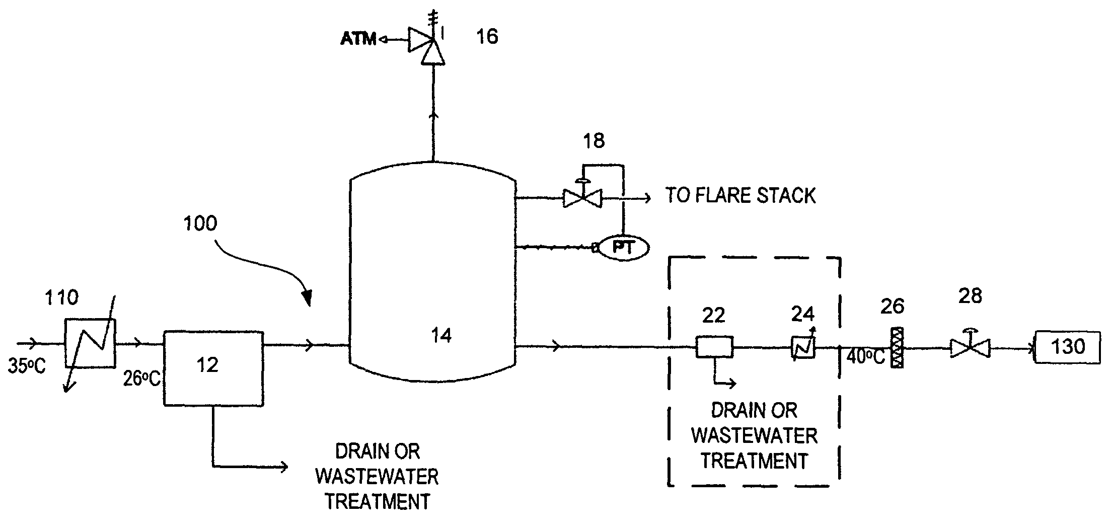
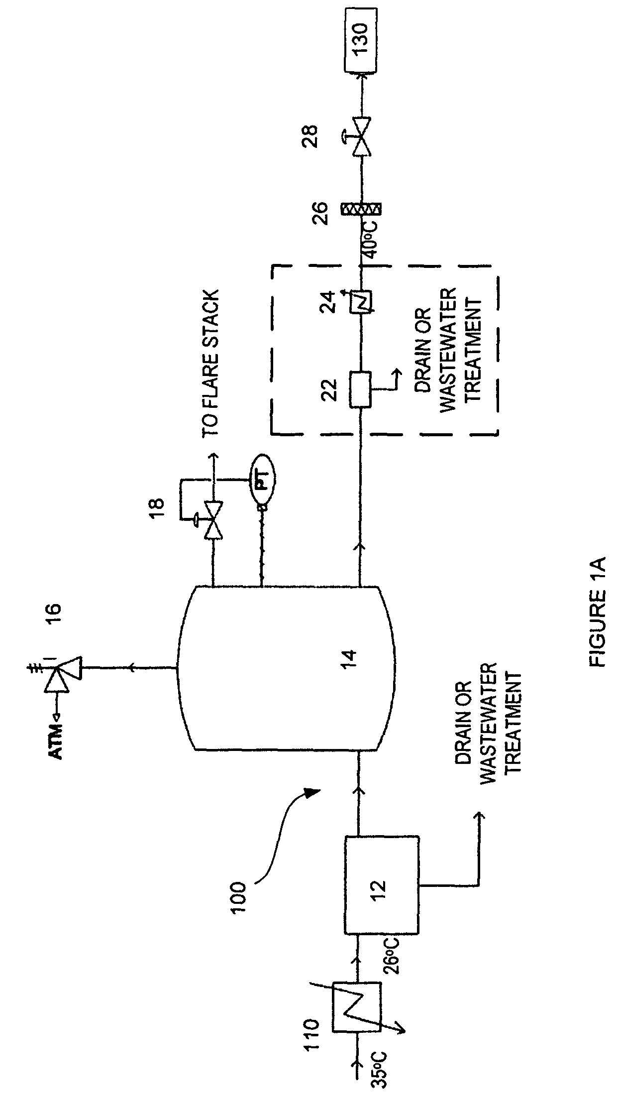
[0227]The following defines characteristics of a homogenization chamber according to one embodiment of the invention.

[0228]In one embodiment, a homogenization chamber provides sufficient storage to allow for blending of the product gas so short-term variability in gas quality is substantially minimized, wherein the homogenization chamber is located outside where it will be exposed to snow, rain and wind load.

Functional Requirements

[0229]Input gas can be highly toxic and flammable and thus the following required safety features can be considered during the design of the homogenization chamber.

[0230]For example, the homogenization chamber is designed to meet following functional requirements.

[0231]

Normal / Maximum inlet temperature35 C. / 40 C.Normal operating pressure3.0 psigNormal / Maximum gas inlet flow rate7200 Nm3 / hr / 9300 Nm3 / hrNormal / Maximum gas outlet flow rate7200 Nm3 / hr / 9300 Nm3 / hrRelative humidity60%-100%Storage volume of tank290 m3Operating gas Volume (Range)0-290 m3Mechanical d...

example 2

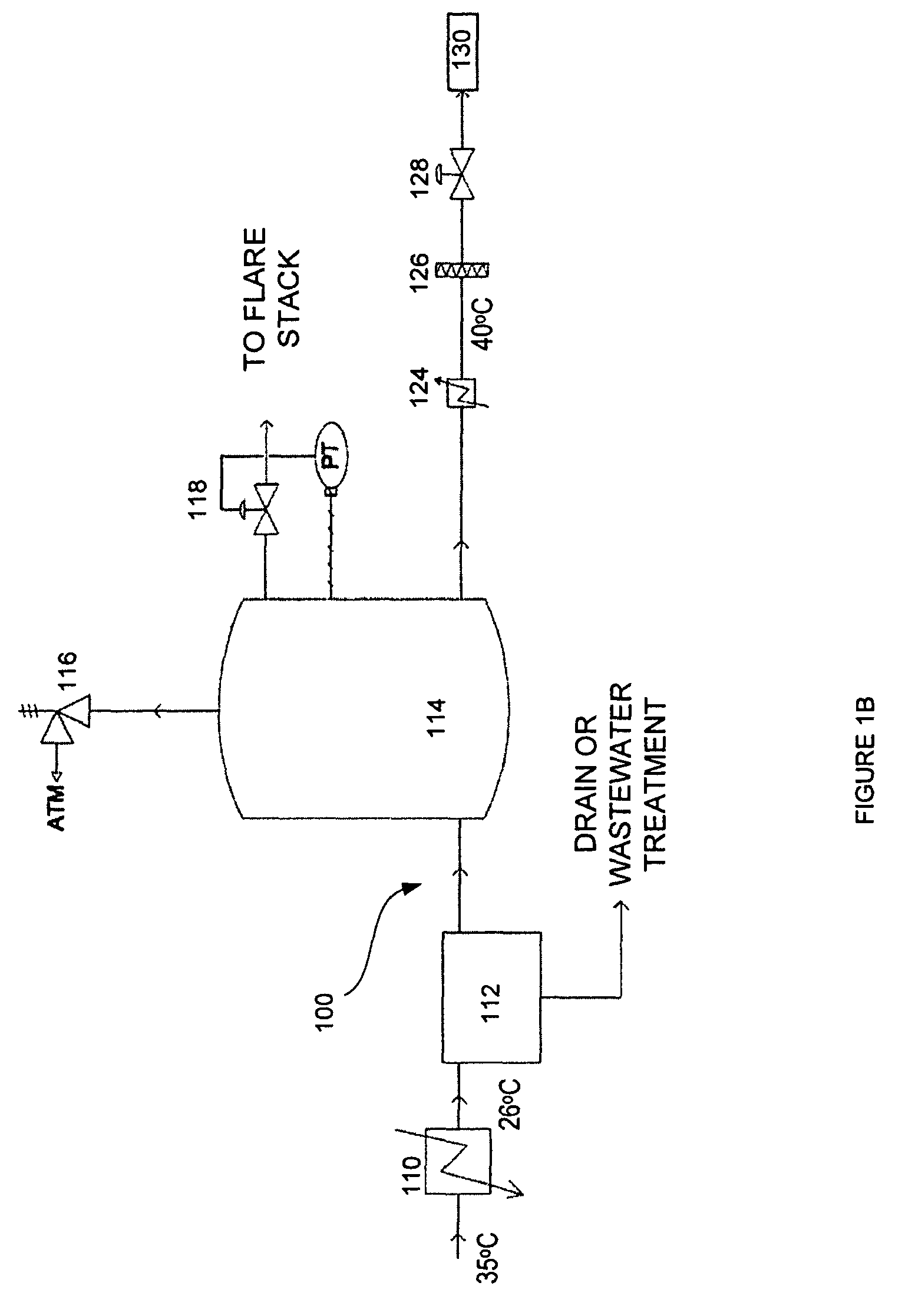
[0257]The following defines characteristics of a homogenization chamber according to one embodiment of the invention.

[0258]In one embodiment of the invention, a homogenization chamber provides sufficient storage to allow for blending of the gas so that short-term variability in gas quality and pressure is minimized, wherein the homogenization chamber is located outside where it will be exposed to snow rain and wind load.

[0259]The homogenization chamber support structure interfaces with a concrete foundation. The homogenization chamber is free-standing and the dimensions of the homogenization chamber are designed to meet mechanical engineering requirements. The gas homogenization chamber typically comprises one single tank, which is erected on-site.

[0260]In one embodiment, some water condenses out of the gas, so a bottom drain nozzle is included in the design of the homogenization chamber for this purpose. To assist in draining the homogenization chamber, it is required that the homo...

example 3

[0283]The following provides functional requirements for a gas blower according to one embodiment of the invention.

[0284]In one embodiment, the gas blower includes a gas cooler and is to be used to withdraw gas from a plasma gasification system. The gas blower is configured to provide adequate suction through all the equipment and piping as per specifications described below.

Functional Requirements

[0285]Input gas is flammable and will create an explosive mixture with air, thus, in one embodiment of the invention all service fluid, i.e. seal purge, is done with Nitrogen. In one embodiment of the invention, the blower is operated through a variable speed drive (VSD) within the flow range of 10% to 100%.

[0286]Engineering of the system will be done with good engineering practice and following all applicable provincial and national codes, standards and OSHA guidelines. The blower is operated through a variable speed drive (VSD) within the flow range of 10% to 100%.

[0287]The gas blower is...


PUM

PropertyMeasurementUnit
temperatureaaaaaaaaaa
pressuresaaaaaaaaaa
temperatureaaaaaaaaaa

Abstract

A system and process for gas homogenization is disclosed. This has application in the areas of generation of gas and its conversion to electricity in downstream applications. The homogenization system minimizes variance in the gas characteristics (composition, flow, pressure, temperature), thereby rendering a steady stream of gas of consistent quality to the downstream machinery. This homogenization system can be adjusted to optimize the output gas stream for specific end-applications, or to optimize the output gas stream for different input feedstocks. This ensures that overall conversion efficiencies are maximized while keeping the process cost-effective. Such a uniform, steady output gas stream has a wide range of applications in the broad areas of generation of electricity (e.g. using internal combustion engines and combustion turbine engines), chemical synthesis (e.g. of compounds such as ethanol, methanol, hydrogen, methane, carbon monoxide, hydrocarbons), fuel-cell technologies and in polygeneration processes (processes that result in co-production of electricity and synthetic fuels).

Description

CROSS REFERENCE TO RELATED APPLICATIONS[0001]This application claims benefit of priority under 35 U.S.C. §119(e) from U.S. Provisional Application Ser. No. 60 / 798,223, filed May 5, 2006. This application also claims benefit of priority to International Patent Application No. PCT / CA2006 / 000881, filed Jun. 5, 2006. This application also claims benefit of priority under 35 U.S.C. §119(e) from U.S. Provisional Application Ser. No. 60 / 864,116, filed Nov. 2, 2006. This application also claims benefit of priority under 35 U.S.C. §119(e) from U.S. Provisional Application Ser. No. 60 / 911,179, filed Apr. 11, 2007. This application also claims benefit of priority under 35 U.S.C. §119(e) from U.S. Provisional Application Ser. No. 60 / 797,973, filed May 5, 2006. The contents of all of the aforementioned applications are hereby expressly incorporated by reference in their entirety and for all purposes.FIELD OF THE INVENTION[0002]The invention pertains to the field of gas production and conversion ...

Claims


Application Information

Patent Timeline
Patent Type & Authority Patents(United States)
IPC IPC(8): B01D50/00B01F23/10
CPCC10J3/18C10J3/34C10J3/82C10J3/84C10J2300/0946Y02E20/16C10J2300/1618C10J2300/165C10J2300/1693Y02E20/18C10J2300/1238C07C29/1518C07C41/09C10J3/00C10L3/00Y02E50/30C07C43/046C07C31/04C07C31/08G05D27/00
Inventor TSANGARIS, ANDREASSWAIN, MARGARET
Owner PLASCO ENERGY GROUP INC
Why Eureka
Try Eureka