MEMS device with surface having a low roughness exponent

a technology of roughness exponent and mems device, which is applied in the direction of deaf-aid sets, electrical transducers, transducer details, etc., can solve the problems of yield loss, reliability failure, yield loss, etc., and achieve the effect of reducing the effect of device performan

Active Publication Date: 2012-03-06
INVENSENSE
View PDF9 Cites 7 Cited by
  • Summary
  • Abstract
  • Description
  • Claims
  • Application Information

AI Technical Summary

Benefits of technology

[0009]To further improve performance, at least one of the backplate surface and diaphragm surface may have a root mean squared (RMS) roughness that is greater than about 1 nanometer. Some embodiments also may form an organic coating on at least one of the backplate surface and diaphragm surface to reduce surface energy. Among other things, the organic coating may be based on one of a fluorocarbon and hydrocarbon.
[0014]Since the diaphragm moves in response to an acoustic signal, the diaphragm / backplating spacing changes dynamically. In normal operation, a plurality of water based droplets may form between the diaphragm surface and the backplate surface. If one or more droplets simultaneously contacts the diaphragm and the backplate, this dynamic motion is affected and device performance is degraded. This result occurs because the surface tension of droplets that bridge the gap between the diaphragm and the backplate imposes a force that alters the spacing. As the amount of wetting of the droplet onto the diaphragm and / or the backplate increases, droplet surface tension pulls the diaphragm closer to the backplate, ultimately causing stiction. Various embodiments reduce wetting of the plurality of droplets onto the diaphragm and backplate and mitigates their effect on device performance. It creates surface-droplet interface conditions that cause the plurality of droplets to de-wet after contact. Thus, the diaphragm can return to the rest position and respond to the acoustic signal without being impeded by the droplets.

Problems solved by technology

Consequently, when exposed to humidity, their surfaces may stick together.
This phenomenon is known in the art as “stiction,” which is a significant cause of yield loss and reliability failures in a wide variety of MEMS products.

Method used


Image

  • MEMS device with surface having a low roughness exponent
  • MEMS device with surface having a low roughness exponent
  • MEMS device with surface having a low roughness exponent

Examples


Embodiment Construction

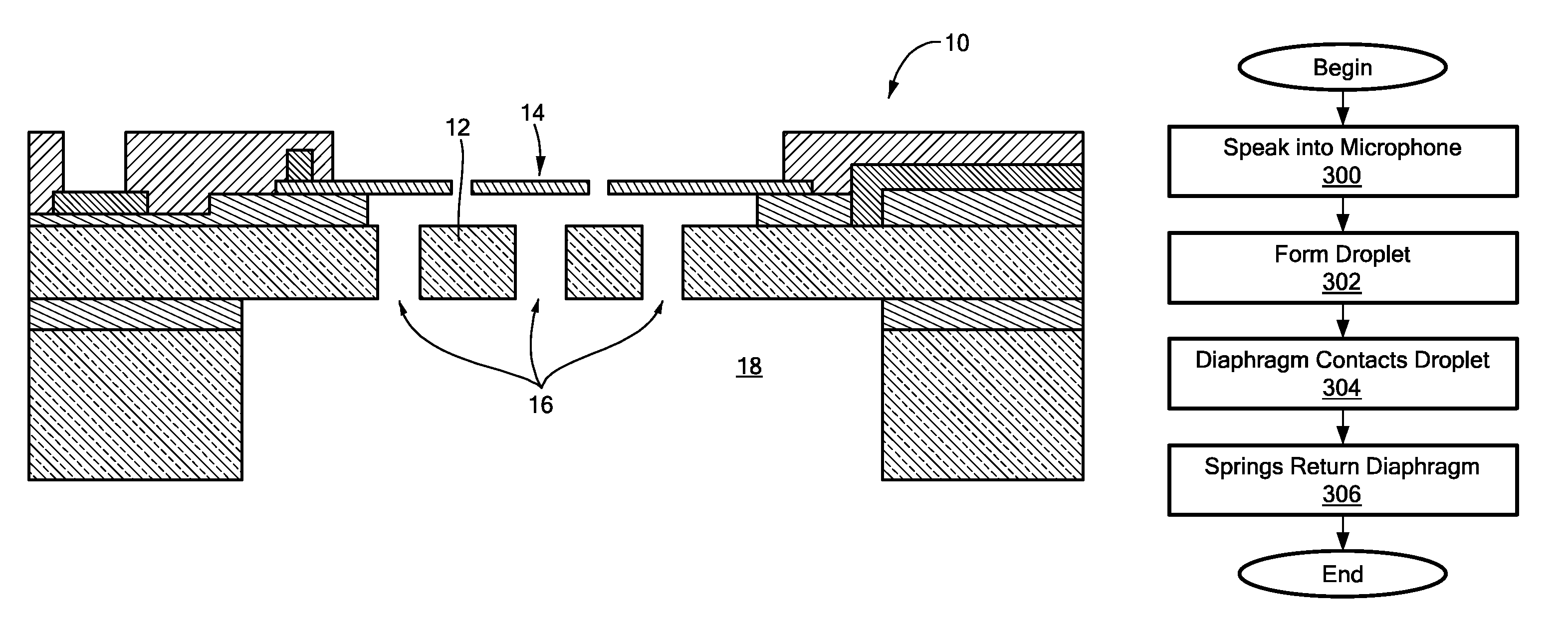
[0020]Illustrative embodiments of the invention reduce stiction problems in open package MEMS devices, such as microphones and pressures sensors. To that end, one or both of the opposing surfaces of the diaphragm and backplate have a plurality of surface features, such as peaks, ridges, valleys, and cavities, that minimize the wetting ability of a water droplet. These surface features effectively follow principles similar to those of the so-called “lotus flower effect.”

[0021]Specifically, various embodiments process the facing surfaces of one or both of the diaphragm and backplate to have a Hurst exponent (also known as the “roughness exponent”) that is less than or equal to about 0.5. Details of illustrative embodiments are discussed below.

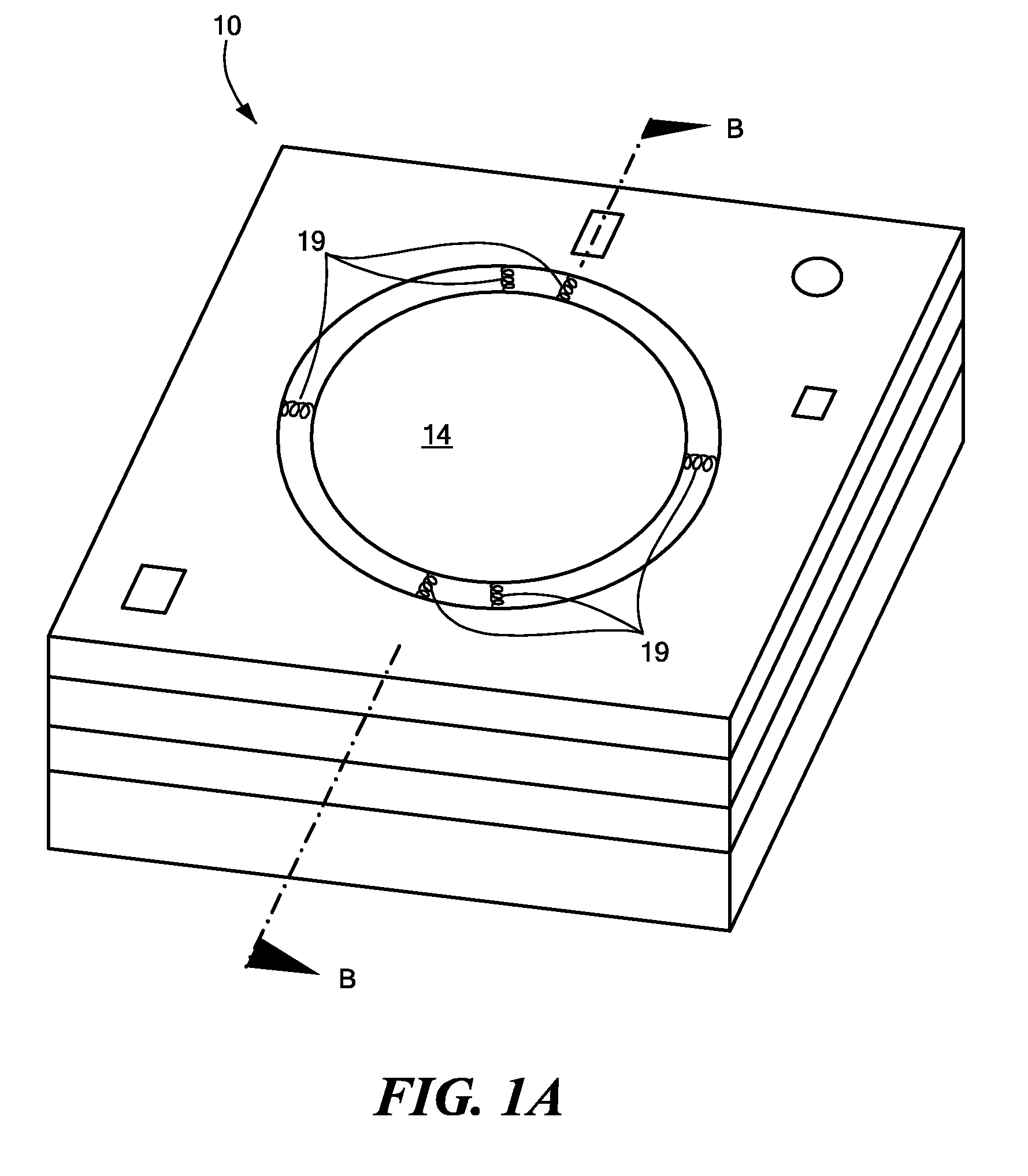
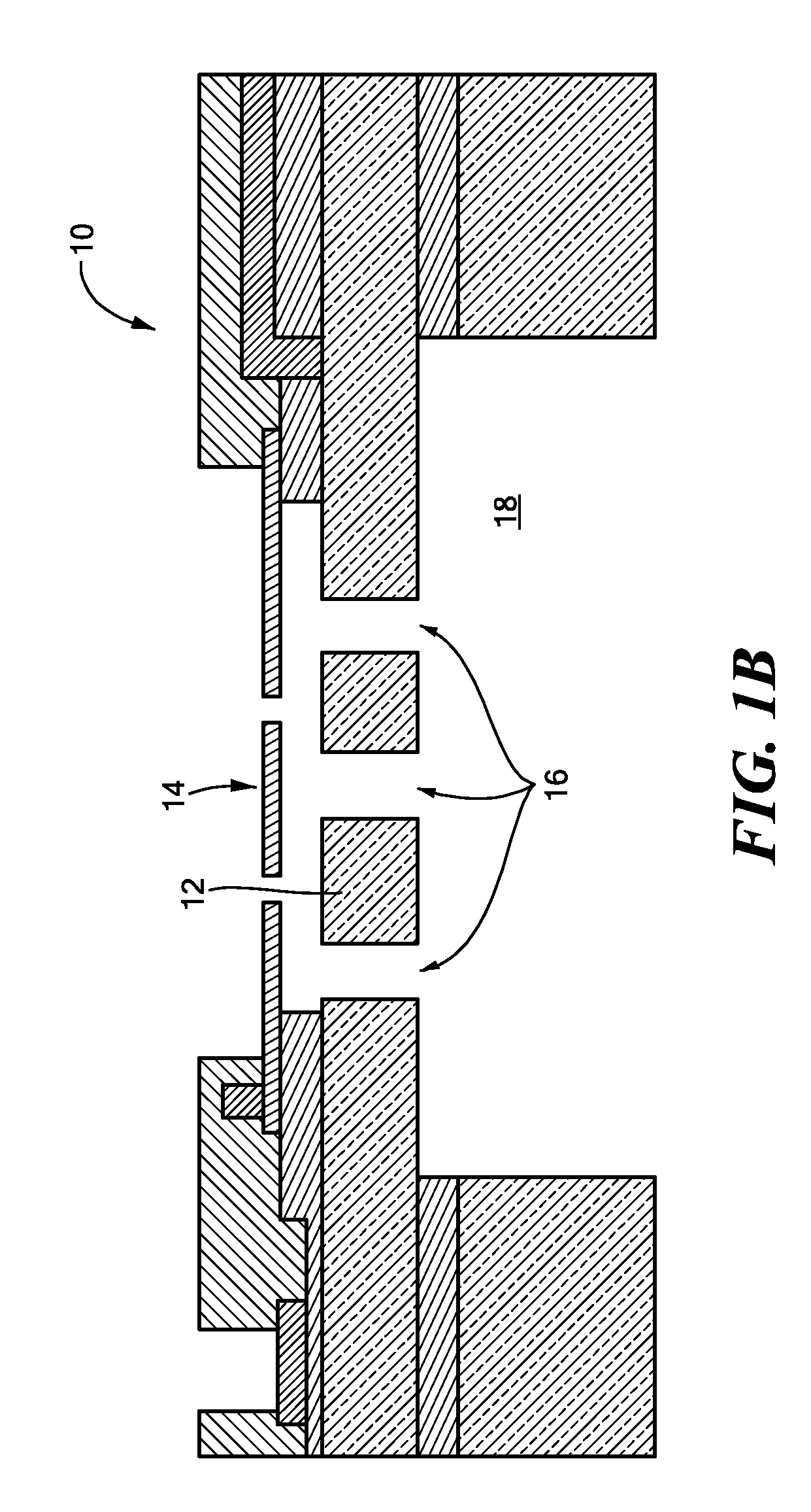
[0022]FIG. 1A schematically shows a top, perspective view of a microphone 10 (also referred to as a “microphone chip 10”) that may be fabricated in accordance with illustrative embodiments of the invention. This microphone 10 is an example of an ...


PUM


Abstract

A MEMS microphone has a backplate and a movable diaphragm that together form a variable capacitance. The backplate has a backplate surface and, in a corresponding manner, the diaphragm has a diaphragm surface that faces the backplate surface. At least one of the backplate surface and the diaphragm surface has at least a portion with a Hurst exponent that is less than or equal to about 0.5.

Description

PRIORITY[0001]This patent application claims priority from provisional U.S. patent application No. 60 / 888,417, filed Feb. 6, 2007, entitled, “OPEN PACKAGE DEVICE WITH ROUGHENED SURFACE,” and naming John R. Martin as inventor, the disclosure of which is incorporated herein, in its entirety, by reference.RELATED APPLICATION[0002]This patent application is related to U.S. patent application Ser. No. 11 / 538,281, filed Oct. 3, 2006, entitled, “MEMS DEVICE WITH ROUGHENED SURFACE AND METHOD OF PRODUCING THE SAME,” and naming Martin, Nunan, Chen, Kuang, and Zhang as inventors, the disclosure of which is incorporated herein, in its entirety, by reference.[0003]This patent application also is related to U.S. Pat. No. 6,674,140, filed Jan. 29, 2001, U.S. Pat. No. 7,220,614, filed Jun. 9, 2003, both entitled, and U.S. application Ser. No. 11 / 786,515, all entitled “PROCESS FOR WAFER LEVEL TREATMENT TO REDUCE STICTION AND PASSIVATE MICROMACHINED SURFACES AND COMPOUNDS USED THEREFOR,” and naming J...

Claims


Application Information

Patent Timeline
Patent Type & Authority Patents(United States)
IPC IPC(8): H04R11/02H01L21/00
CPCH04R19/005
Inventor MARTIN, JOHN R.
Owner INVENSENSE
Why Eureka
Try Eureka