
Optical transmitter error reduction using receiver feedback

a technology of optical transmitter and receiver, applied in the field of optical communication networks, can solve problems such as the impairment of the ability to successfully transmit data from an optical transmitter to an optical receiver through an optical communication channel, the introduction of bias control based on nonlinearities, and the degradation of the performance of the communications system. to achieve the effect of reducing the transmitter error

Active Publication Date: 2012-03-06
CIENA
View PDF11 Cites 15 Cited by
  • Summary
  • Abstract
  • Description
  • Claims
  • Application Information

AI Technical Summary

Benefits of technology

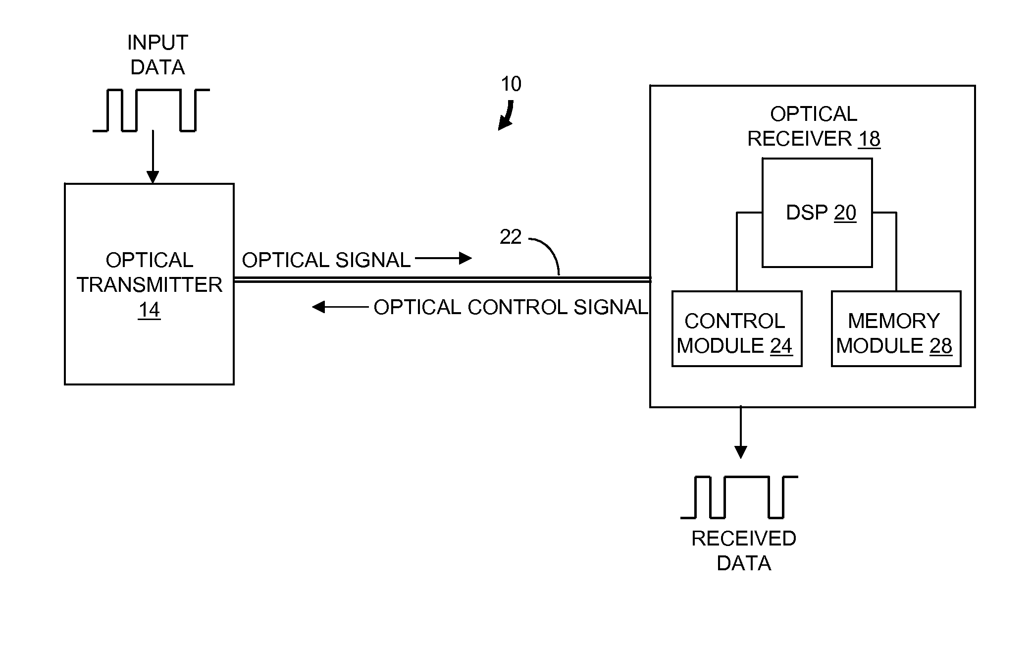
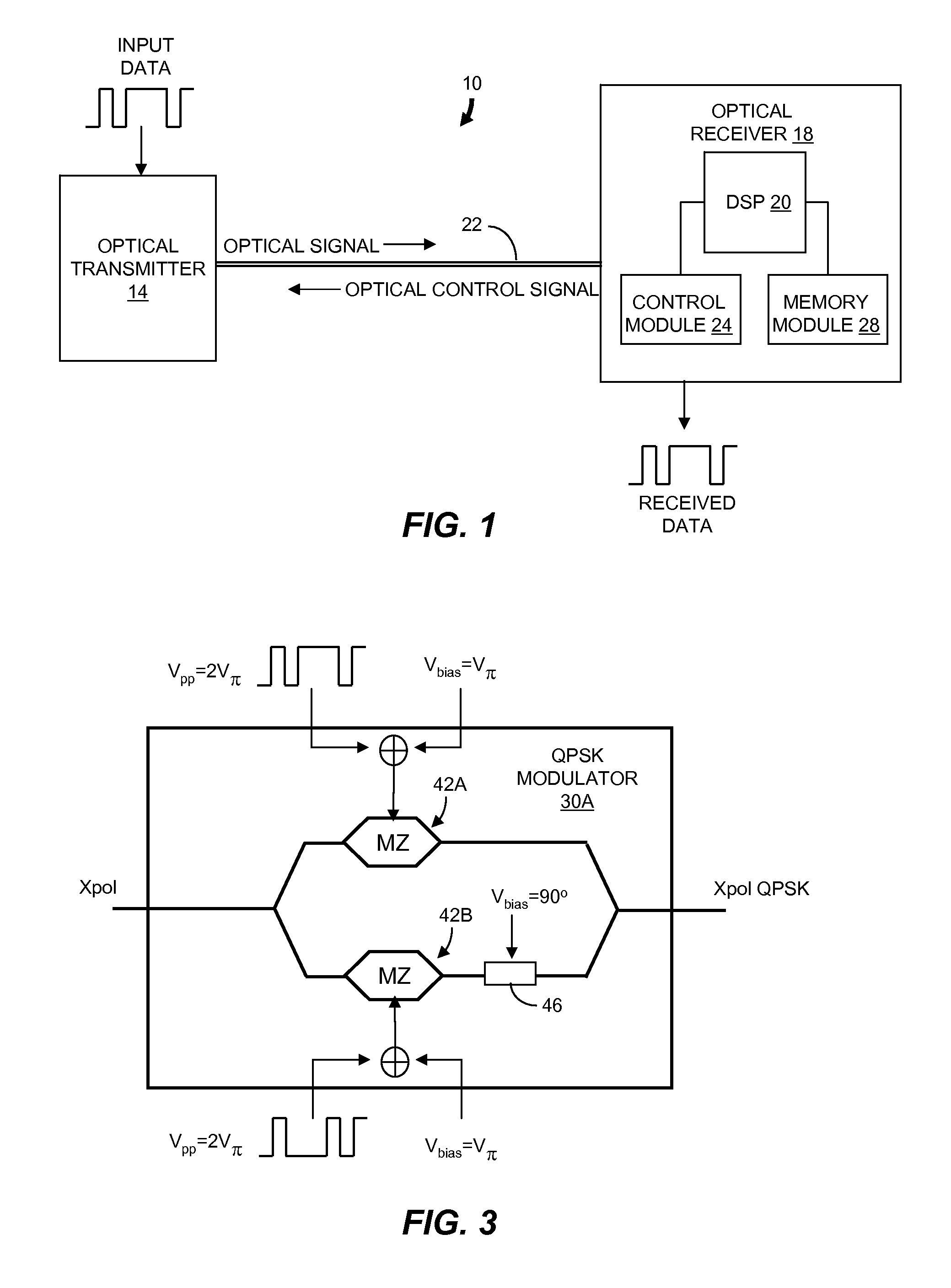
The invention is about reducing transmitter error in optical communications channels. It involves processing an optical signal from an optical transmitter with impairment due to transmitter error to generate a digitally-equalized signal. The nonlinear characteristic of this signal is determined, and an optical control signal is transmitted to the optical transmitter to modify the nonlinear characteristic and change the impairment. This results in a more accurate and reliable optical signal transmission. The invention also includes an optical receiver that stores data derived from a prior digital sampling of the optical signal and uses it to generate a digitally-equalized signal. The nonlinear characteristic of this signal is determined, and a control signal is transmitted to the optical transmitter to adjust the transmitter parameter and reduce the impairment of the optical signal due to the transmitter error. Overall, the invention improves the quality and reliability of optical communications.

Problems solved by technology

The ability to successfully transmit data from an optical transmitter to an optical receiver through an optical communications channel can be impaired by errors introduced at the transmitter.
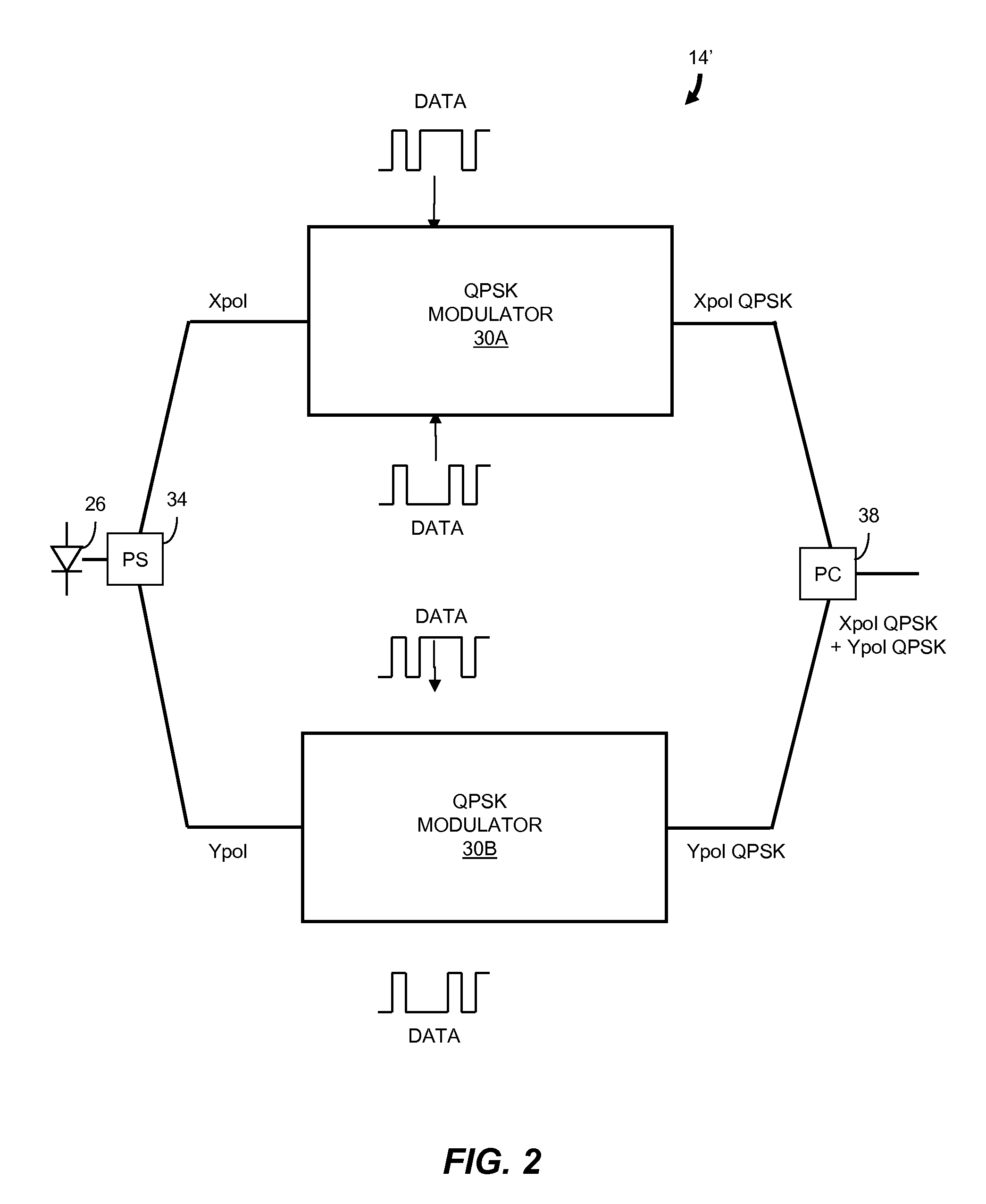
Any variation from the 90° bias is referred to as transmit quadrature error and can result in degradation of the communications system performance.
Although bias control can be used to reduce quadrature error, and to control gain and gain balancing, bias control can introduce errors based on nonlinearities in the drive controls and chirp in the MZ modulators.
Such errors can be difficult and expensive to detect at the optical transmitter.
Any error in the bias voltage Vbias applied to a MZ modulator to achieve extinction results in a DC tone in the transmitted optical signal.
This error is referred to as carrier leakage and degrades the optical signal to noise ratio (OSNR).
Sampling phase errors occur if the BPSK signals are not time-synchronized to within a small fraction of the data rate of the signal applied to the two MZ modulators.
Sampling phase error leads to degradation of the bit error rate (BER) at the optical receiver.
Quadrature error, carrier leakage, IQ timing error and the difference in the DC gain of the I and Q channels (IQ gain error) at the optical transmitter generally vary in time due to environmental changes.
Detection of these errors at the optical transmitter is difficult and requires expensive and complex implementations.

Method used


Image

  • Optical transmitter error reduction using receiver feedback
  • Optical transmitter error reduction using receiver feedback
  • Optical transmitter error reduction using receiver feedback

Examples


Embodiment Construction

[0021]In brief overview, the invention relates to a method of reducing transmitter error in an optical communications channel. In one embodiment, an optical signal transmitted from an optical transmitter is processed to generate a digitally-equalized signal. A nonlinear characteristic indicative of a transmitter error is determined from the digitally-equalized signal. A control signal comprising data based on the nonlinear characteristic is sent to the optical transmitter and used to modify a transmitter parameter to cause a change in the nonlinear characteristic. The method provides for the reduction or elimination of certain transmitter errors. For example, quadrature error, carrier leakage and IQ timing error for a QPSK optical signal can be reduced. Consequently, the reach of the optical communications system can be increased and the cost to customers or subscribers reduced. The method is particularly useful for next generation systems (e.g., 100 Gbit / s systems) in which transmi...


PUM


Abstract

Described is a method of reducing transmitter error in an optical communications channel. An optical signal transmitted from an optical transmitter that has impairment due to transmitter error is processed to generate a digitally-equalized signal. A nonlinear characteristic of the digitally-equalized signal that relates to the transmitter error is determined. An optical control signal comprising data that are based on the nonlinear characteristic is transmitted to the optical transmitter. The optical transmitter modifies a transmitter parameter in response to the optical control signal to change the nonlinear characteristic and thereby reduce the impairment.

Description

FIELD OF THE INVENTION[0001]The invention relates generally to optical communications networks. More particularly, the invention relates to a method and system for reducing optical transmitter signal error in an optical signal transmitted through an optical communications network and detected at an optical receiver.BACKGROUND OF THE INVENTION[0002]The need for higher data rates has put significant demands on optical communications. Requirements on network performance continue to increase and component specifications have become more stringent. Optical networks employing coherent detection receivers have considerable advantages over direct detection receivers for high data rate communications. One type of coherent detection used to achieve higher bit rate communications is quadrature carrier modulation. Data to be transmitted are used to modulate an in-phase signal and a quadrature signal for each of two orthogonal polarizations of an optical signal, enabling data rates that are four...

Claims


Application Information

Patent Timeline
Patent Type & Authority Patents(United States)
IPC IPC(8): H04B10/08H04B10/00H04B10/04H04B10/12
CPCH04B10/0799
Inventor SUN, HANWU, KUANG TSANROBERTS, KIM B.
Owner CIENA
Learn More