Catheter with common guide wire and indicator lumen

a catheter and indicator lumen technology, applied in the direction of catheters, instruments, diagnostic recording/measuring, etc., can solve the problems of reducing the accuracy of measurement, achieve the effect of convenient operation, improve the accuracy of blood flow measurement in thermodilution measurement, and reduce the accuracy of measuremen

Active Publication Date: 2012-03-13
TRANSONIC SYST
View PDF24 Cites 2 Cited by
  • Summary
  • Abstract
  • Description
  • Claims
  • Application Information

AI Technical Summary

Benefits of technology

[0012]As a consequence of thermal transfer, such as conduction or radiation within the catheter, the dilution thermal sensor in the retrograde catheter will register temperature changes, or effects, both by the injectate (indicator) passing through the catheter and the diluted blood flowing past the catheter. In this case, inside cooling of the dilution thermal sensor falsely increases the area under the resulting dilution curve and thus decreases the accuracy of the measurement.
[0013]The present invention also provides for measurement of the blood flow during the TIPS procedure, wherein the measurements can be conveniently performed by a retrograde catheter, introduced for example through the jugular vein, through the vena cava, and through the hepatic vein.
[0014]The measurements can be performed before intervention, after the shunt construction, in the shunt and in the vena porto (portacaval shunt). In this case, the retrograde catheter can be introduced through the hepatic vein, through the shunt and into the vena porta. The advantage of a blood flow measurement during the intervention is the ability to change the shunt flow if the shunt flow is not adequate.
[0015]The present confi...

Problems solved by technology

In this case, inside cooling of the dilution thermal sensor falsely increases the a...

Method used


Image

  • Catheter with common guide wire and indicator lumen
  • Catheter with common guide wire and indicator lumen
  • Catheter with common guide wire and indicator lumen

Examples


Embodiment Construction

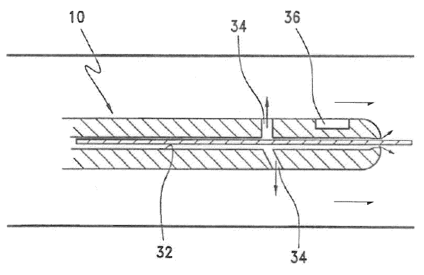
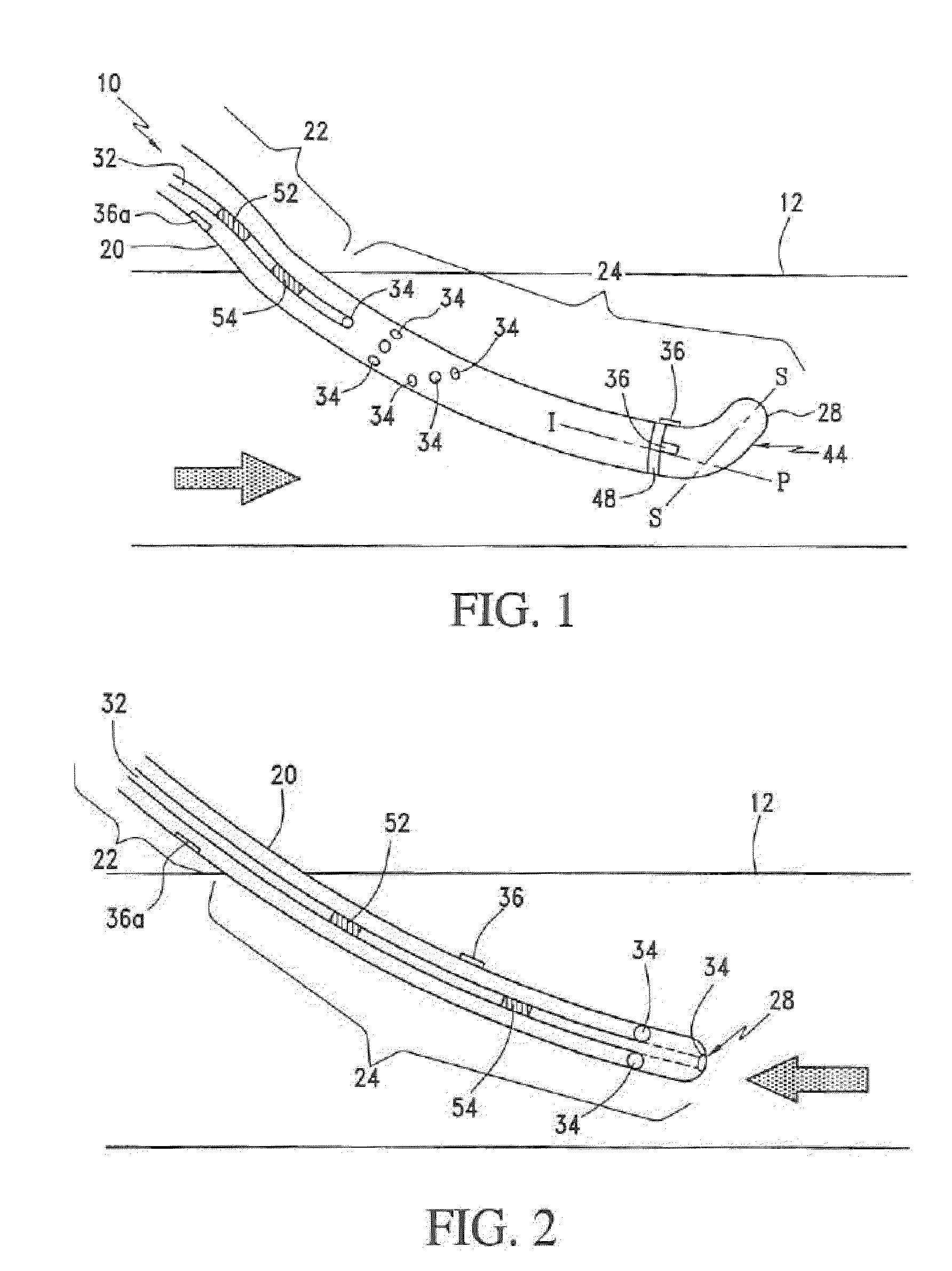
[0040]Referring to FIGS. 1 and 2, the present indicator dilution catheter 10 is shown operably located in an arterio-venous (A-V) shunt 12. The A-V shunt 12 has a blood flow shown by the direction of the arrows, the catheter 10 includes an elongate body 20 having an extravascular portion 22 and an intravascular portion 24. The extravascular portion 22 being that portion or length of the body 20 that is not operably located within the A-V shunt 12 to contact the blood flow in the shunt. The intravascular portion 24 is that portion or length of the body 20 that is operably located within the A-V shunt 12 and contacts the blood flow in the shunt. The body 20 includes a proximal end, a distal end 28, an indicator (injectate) lumen 32, an injection port(s) 34 and a dilution sensor 36 for detecting passage of the injected indicator in the blood flow in the A-V shunt 12. That is, the dilution sensor measures a temperature of the diluted blood flow resulting from introduction of the injecta...


PUM


Abstract

A catheter for retrograde orientation in a blood flow is used to determine the blood flow rate by thermodilution measurements. The determination of the blood flow rate accommodates injectate induced thermal influences on a dilution thermal sensor, wherein the thermal influences can occur prior to introduction of the injectate into the blood flow.

Description

CROSS REFERENCE TO RELATED APPLICATIONS[0001]The present application is a continuation of U.S. Ser. No. 10 / 079,006 filed Feb. 20, 2002, now U.S. Pat. No. 6,623,436.STATEMENT REGARDING FEDERALLY SPONSORED RESEARCH OR DEVELOPMENT[0002]This invention was made with government support under Phase I SBIR (Small Business Innovative Research Grant # 1 R43 DK55444-01A2 awarded by the National Institutes of Health. The government has certain rights in the invention.BACKGROUND OF THE INVENTIONField of the Invention[0003]The present invention relates to blood flow measurement by thermodilution measurement, and more particularly to compensating for an injectate induced thermal effect on a thermal sensor in a retrograde catheter.[0004]In native A-V fistulae, any stenosis is often located at the arterial portion of the vascular access or A-V shunt. The existence of a stenosis in the vascular access typically requires intervention to restore sufficient flow, or at least reduce the rate of occlusion...

Claims


Application Information

Patent Timeline
IPC IPC(8): A61B5/02G01F1/00G01F1/708G01F1/68G01P5/18A61B5/028
CPCA61B5/028A61B5/6855
Inventor KRIVITSKI, NIKOLAI M.KISLUKHIN, VICTOR V.
Owner TRANSONIC SYST
Why Eureka
Try Eureka