Composite shingle

a technology of composite shingles and shingle sheets, which is applied in the field of composite shingles, can solve the problems of uneconomical and less desirable applications in modern building construction, high material and installation costs of slate shingles, and the material cost of slate shingles is much greater than the standard asphalt shingles used, so as to reduce the effective span of the body shell, reduce shear and bending loads, and reduce the amount of material

Inactive Publication Date: 2012-03-20
TAMKO BUILDING PRODS
View PDF93 Cites 35 Cited by
  • Summary
  • Abstract
  • Description
  • Claims
  • Application Information

AI Technical Summary

Benefits of technology

[0008]The rib stiffeners may include a material saving profile having a smaller depth in the mid portion of the stiffener than at the ends, for example, a notched “V” or arched profile. This material saving profile still provides the necessary force transfer and stiffening properties, as well as reduces the amount of material required to manufacture the composite shingle. Generally, rib stiffeners have an orientation with respect to the longitudinal ribs having an angle of incidence less than ninety degrees. The rib stiffeners may be positioned in a centered rectangular lattice pattern or other pattern that creates an adequate framework to support the top-surface of the composite shingle.
[0009]The rib stiffeners can support the body shell and greatly reduce the effective span of the body shell using plate action to reduce shear and bending loads. A reduced effective span allows the body shell thickness to be less, thereby further reducing the material required to make the composite shingle. Additionally, rib stiffeners reduce the unbraced length of the bottom edge of the longitudinal ribs. When the body shell is subjected to an uplift force due to wind loads, the bottom edge of the longitudinal ribs is subjected to compression and the composite shingle is vulnerable to web buckling. The reduced unbraced length of the bottom edge increases the composite shingles resistance to buckling caused by uplift. Further, stiffening the longitudinal ribs allows the longitudinal ribs to be narrower; thus, providing the ability to further reduce the amount of raw material required per shingle.
[0011]An additional embodiment of the composite shingle further comprises alignment aids. Alignment aids may be a laying line, spacing nibs and / or a scale on the top surface. An embodiment of composite shingle includes an alignment aid comprising a laying line. A laying line includes a width that facilitates the application of a second course of composite shingles on top of an underlying course of composite shingles by providing a guide that allows for proper spacing between each of the composite shingles on the second course and ensuring second course is properly aligned with first course. Alternatively, the alignment aid may include at least two spacing nibs. The spacing nibs extend outwardly from the left-side wall, the first side wall, or both side walls. The spacing nibs aid an installer in properly spacing the shingles horizontally when installing composite shingles on the roof. Certain embodiments of the composite shingle include at least two nibs on one side wall. Two spacing nibs on one side wall help square the first shingle in relation to a second shingle horizontally adjacent to it. Additionally, the spacing nibs may be used in concert with the scale located on the top surface of the body shell to help an installer create offset composite shingle patterns or help make sure all the composite shingles have a uniform tab exposure.

Problems solved by technology

However, the use of natural materials often has drawbacks that make them less desirable and uneconomical for many applications in modern building construction.
Natural slate is coveted for its appearance and durability; however, slate is a very heavy building material with high material and installation costs.
The material cost for slate shingles is much greater than the standard asphalt shingles used in most residential construction and its use in certain applications is nearly cost prohibitive.
In addition to the higher material price, slate shingles have high installation costs because the shingles must be hand nailed due to the tendency of slate to chip or split under the impact of a nail driven by a pneumatic nail gun.
Traditional roof construction may not always be adequate to support the weight of slate shingles; as a result, the structure supporting a slate roof must be stronger to accommodate the increased loads.
The increased design load associated with slate shingles ultimately increases entire structure costs as the extra load in the roof must be carried all the way down to the foundations.
Wood shake shingles are similar in weight to common asphalt shingles and do not require increased structure costs; however, wood shingles also have some competitive drawbacks in modern construction.
Wood shingles do not have an equivalent life span to asphalt shingles; thus, they need to be replaced much sooner.
Further, wood shingles are typically more expensive than asphalt shingles thereby increasing the up front material costs.
Wood shingles without sufficient sun exposure are subject to the growth of moss and subsequent rot.
Wood shingles also absorb water which results in a tendency to curl and not remain flat on the roof.
All of these factors result in increased maintenance costs.
Further, wood shingles do not have the fire resistance of asphalt shingles and, in fact, may create a fire hazard as wood shingles are often dry and can actually accelerate a fire if an errant airborne cinder lands on the roof.
Composite shingles will not rot and often have at least a fifty-year life span resulting in low maintenance costs during a roofs life span.
However, known composite shingles still have performance defects.
For example, when shingles include a cavity under the top surface to achieve a greater, more realistic height while still maintaining a low shingle weight, the top surface often deforms when the composite shingles sit in the sun for prolonged periods of time, thereby creating sag in the middle of the shingle or between the surface supports.
In addition, by only including lengthwise support rails, the shingle is still vulnerable to buckling upon application of an uplift force load due to wind loads.

Method used


Image

  • Composite shingle
  • Composite shingle
  • Composite shingle

Examples


Embodiment Construction

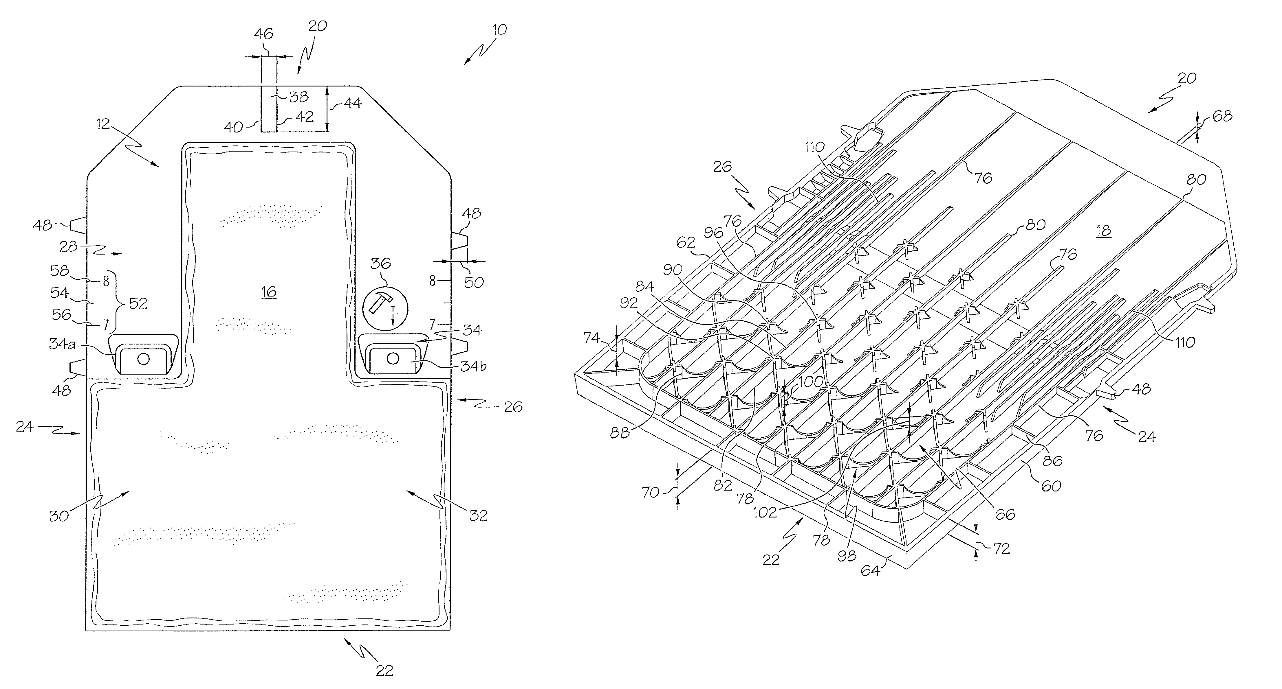
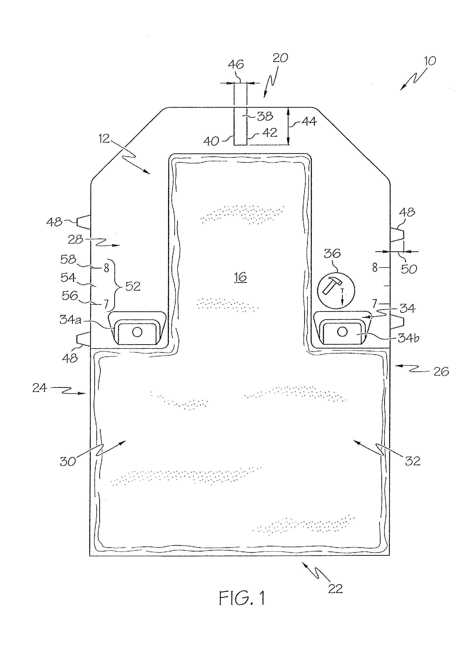
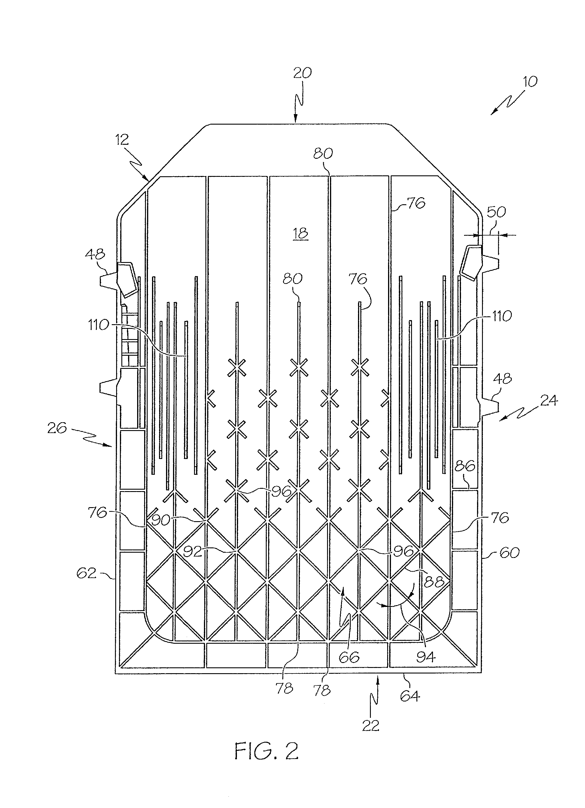
[0020]The invention will now be described with reference to the drawing figures, in which like reference numerals refer to like parts throughout. For purposes of clarity in illustrating the characteristics of the present invention, proportional relationships of the elements have not necessarily been maintained in the drawings.

[0021]Referring now to FIGS. 1 and 2, reference numeral 10 generally denotes a composite shingle. Composite shingle 10 may be formed of any suitable material such as, but not limited to, rubber (e.g., ground up tire rubber), polymers such as polyethylene (e.g., various grades, recycled or virgin), fillers (e.g., wood fibers, glass, stone, limestone), asphalt embedded mats, tile, or any or suitable material. Further, composite shingle 10 may be made and cut, or molded, to any shape desired using known techniques. For example, one manner of making composite shingle 10 is through use of a combination mixer and extruder; however, any method to make composite buildi...


PUM

PropertyMeasurementUnit
angle of incidenceaaaaaaaaaa
thicknessaaaaaaaaaa
lengthsaaaaaaaaaa

Abstract

A composite shingle having unitary construction is presented that includes a body shell, a plurality of longitudinal ribs, and a plurality of rib stiffeners. The present composite shingle may also include transverse ribs, a depressed nailing zone, nailing zone ribs, and / or at least one alignment aid. The plurality of rib stiffeners may include a material saving profile. Further, the dimensions of the composite shingle more closely resemble true slate and shake shingles and at least a portion of the outside face of composite shingle may be textured to resemble slate or wood shake shingles.A plurality of assembled composite shingles of the present invention is also claimed as part of this invention. Finally, a method of applying multiple courses of shingles on a roof including the composite shingle of the present invention is presented.

Description

CROSS-REFERENCE TO RELATED APPLICATIONS[0001]NoneBACKGROUND OF THE INVENTION[0002]The use of natural-appearing materials such as slate or wood shake for composite shingles is a very established practice in building construction. These natural materials are coveted for their appearance and material properties. However, the use of natural materials often has drawbacks that make them less desirable and uneconomical for many applications in modern building construction. Natural slate is coveted for its appearance and durability; however, slate is a very heavy building material with high material and installation costs. The material cost for slate shingles is much greater than the standard asphalt shingles used in most residential construction and its use in certain applications is nearly cost prohibitive. In addition to the higher material price, slate shingles have high installation costs because the shingles must be hand nailed due to the tendency of slate to chip or split under the i...

Claims


Application Information

Patent Timeline
Patent Type & Authority Patents(United States)
IPC IPC(8): E04D1/00E04D1/34
CPCE04D1/205E04D1/20
Inventor SHADWELL, PETERBRUMMETT, BRANDON LEE
Owner TAMKO BUILDING PRODS
Why Eureka
Try Eureka