Method of manufacturing wiring substrate

a manufacturing method and wiring technology, applied in the direction of printed circuit manufacturing, printed circuit aspects, chemistry apparatus and processes, etc., can solve the problems of high clock frequency operation instability, difficult to obtain sufficient density and size reduction, and increase the inductance of the connecting portion, so as to enhance reliability and suppress the occurrence of connecting failures.

Active Publication Date: 2012-03-20
SHINKO ELECTRIC IND CO LTD
View PDF8 Cites 23 Cited by
  • Summary
  • Abstract
  • Description
  • Claims
  • Application Information

AI Technical Summary

Benefits of technology

[0016]Exemplary embodiments of the present invention provide a method of manufacturing a wiring substrate which can form a fine wiring, and furthermore, can suppress an occurrence of a connecting failure and can enhance a reliability.
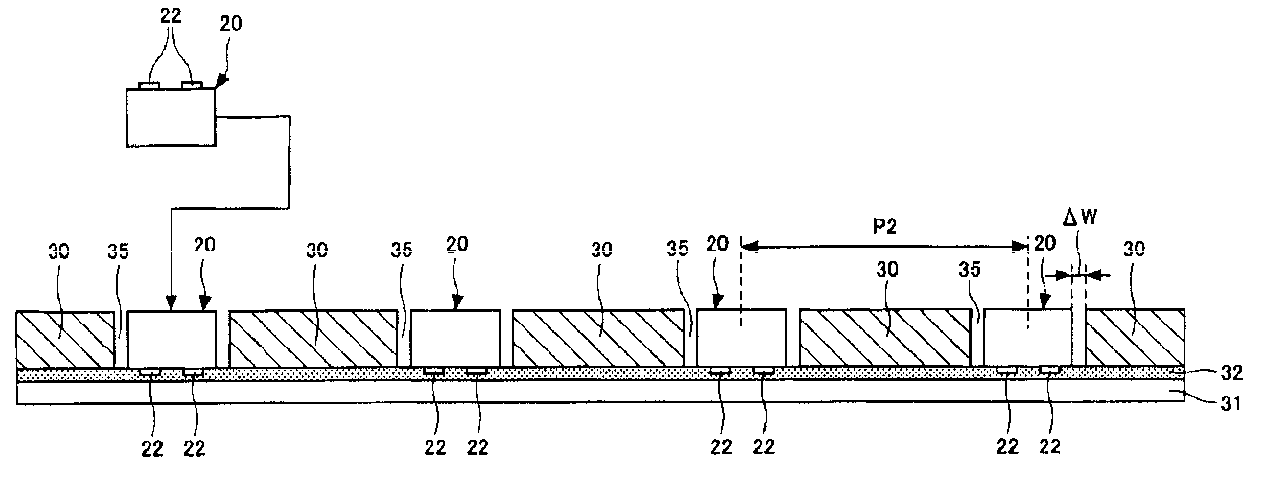
[0024]According to the invention, the chip component is provided in the through opening formed on the reinforcing substrate. Therefore, the resin for fixing the chip component to the reinforcing substrate is disposed in only a clearance portion provided between the chip component formed in the through opening and the reinforcing substrate. Even if a contraction is generated when the resin is cured, accordingly, the chip component is rarely influenced. Thus, it is possible to connect the chip component and the wiring (the build-up layer) reliably and electrically. Moreover, the build-up layer is mainly formed on upper surfaces of the reinforcing substrate and the chip component, and a surface roughness of each of the upper surfaces is lower than that of the conventional resin. Therefore, it is possible to form a fine wiring.

Problems solved by technology

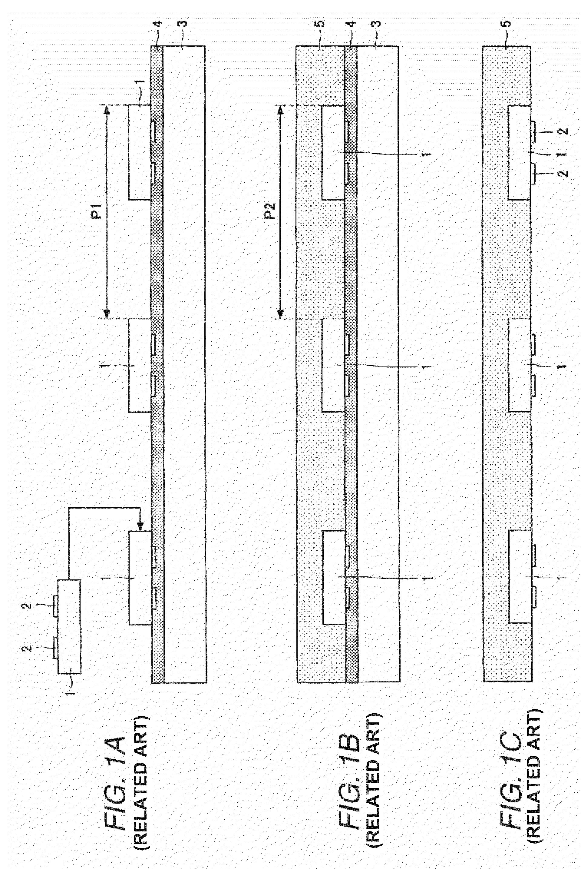
According to the method, however, it is hard to obtain an increase in a density and a reduction in a size which are sufficient.
With a structure in which the chip component and the pad of the build-up wiring layer are connected to each other by using the bump, moreover, there is a problem in that an inductance in the connecting portion is raised, and particularly, an operation at a high clock frequency becomes unstable.
In this case, there is a possibility that a connecting failure of the pad 2 of the semiconductor chip 1 and the first wiring layer 6 might be caused.
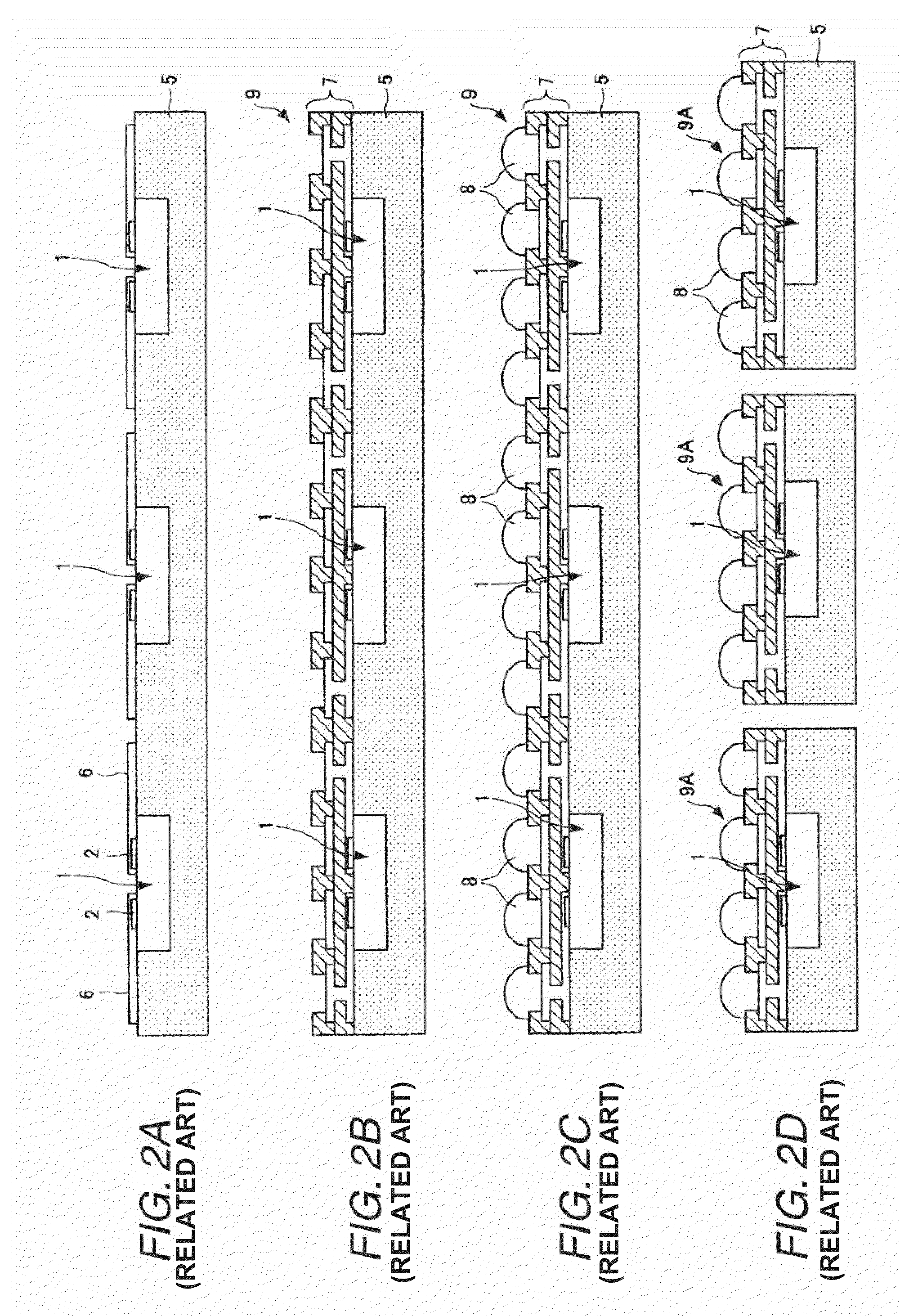
For this reason, the build-up wiring layer 7 cannot be formed with high precision so that it is hard to form a fine wiring.

Method used


Image

  • Method of manufacturing wiring substrate
  • Method of manufacturing wiring substrate
  • Method of manufacturing wiring substrate

Examples


first embodiment

[0046]FIGS. 3A to 9B are views showing a method of manufacturing a wiring substrate according to the invention in accordance with a manufacturing procedure. Description will be given to an example in which a semiconductor chip 20 (formed of silicon) is used as a chip component to be provided (to be included in the wiring substrate.

[0047]In order to manufacture the wiring substrate, first of all, a stiffener substrate 30 (corresponding to a reinforcing substrate) shown in FIG. 3A is prepared. For the stiffener substrate 30, a silicon wafer is used in the embodiment.

[0048]A material of the stiffener substrate 30 is not restricted to silicon but it is also possible to use another material (a resin, a metal or their composite material) which can support (reinforce) a build-up wiring layer 48 constituting a wiring substrate 60 to be manufactured and has a small difference in a thermal expansion from the semiconductor chip 20 to be mounted. Moreover, the stiffener substrate 30 is not alwa...

second embodiment

[0088]Next, description will be given to a second embodiment according to the invention.

[0089]FIGS. 10A to 18B show a method of manufacturing a wiring substrate according to the second embodiment. In FIGS. 10A to 18B, corresponding structures to the structures shown in FIGS. 3A to 9B have the same reference numerals and description thereof will be omitted.

[0090]In the second embodiment, also in the case in which the wiring substrate is manufactured, a stiffener substrate 30 formed by a silicon wafer is first prepared as shown in FIG. 10A. Also in the embodiment, a material of the stiffener substrate 30 is not restricted to silicon but it is also possible to use another material which can support (reinforce) a build-up wiring layer 48 and has a small difference in a thermal expansion from the semiconductor chip 20 to be mounted. Moreover, the stiffener substrate 30 is not always the wafer but a material taking a shape other than the wafer may be used.

[0091]Next, a polishing processin...


PUM

PropertyMeasurementUnit
thickness L1aaaaaaaaaa
thicknessaaaaaaaaaa
thicknessaaaaaaaaaa

Abstract

A method includes the steps of providing a first tape base material on a single side of a stiffener substrate, forming, on the stiffener substrate, a cavity for accommodating a semiconductor chip therein, inserting the stiffener substrate in the cavity and providing the stiffener substrate on the first tape base material, sealing the semiconductor chip and the stiffener substrate with a sealing resin, and removing the first tape base material and forming a build-up layer on a tape removing surface.

Description

TECHNICAL FIELD[0001]The present disclosure relates to a method of manufacturing a wiring substrate, and more particularly to a method of manufacturing a wiring substrate having a structure including a chip component.RELATED ART[0002]In recent years, high density mounting of an electronic component to be incorporated in an electronic apparatus has rapidly been advanced with a demand of an enhancement in a performance or a reduction in a size for the electronic apparatus. Conventionally, there has been employed a method of manufacturing a substrate and a semiconductor chip at separate steps and flip-chip mounting the semiconductor chip on the substrate thus manufactured individually.[0003]According to the method, however, it is hard to obtain an increase in a density and a reduction in a size which are sufficient. For this reason, there has also been proposed a so-called chip built-in substrate in which a chip component is provided on a substrate core portion and a build-up wiring la...

Claims


Application Information

Patent Timeline
Patent Type & Authority Patents(United States)
IPC IPC(8): B29C37/00
CPCH01L21/568H01L21/6835H01L23/16H01L23/3107H01L23/5389H01L24/19H01L24/96H05K1/185H01L25/105H01L2221/68345H01L2224/04105H01L2224/20H01L2924/01029H01L2924/01074H01L2924/01078H01L2924/15311H01L2924/15331H01L2924/30107H05K3/0052H05K3/205H05K3/423H05K3/4602H05K3/4644H05K2201/10674H05K2203/0152H05K2203/0156H05K2203/025H05K2203/0376H05K2203/0733H05K2203/1469H01L2924/01005H01L2924/01006H01L2924/01033H01L2225/1035H01L2225/1058H01L2224/12105H01L2924/181H01L2924/3511H01L2924/00
Inventor SUNOHARA, MASAHIROMURAYAMA, KEIHIGASHI, MITSUTOSHISAKAGUCHI, HIDEAKI
Owner SHINKO ELECTRIC IND CO LTD
Why Eureka
Try Eureka