Rotating electric machine and cooling system for the rotating electric machine
a technology of rotating electric machines and cooling systems, which is applied in the direction of rotating parts of magnetic circuits, magnetic circuit shapes/forms/construction, windings, etc., can solve the problems of increasing the cost of manufacturing motors, the weight of rotating electric machines or and the increase of the cost of manufacturing rotating electric machines. , to achieve the effect of improving the heat discharging properties of stator coil ends
- Summary
- Abstract
- Description
- Claims
- Application Information
AI Technical Summary
Benefits of technology
Problems solved by technology
Method used
Image
Examples
first embodiment
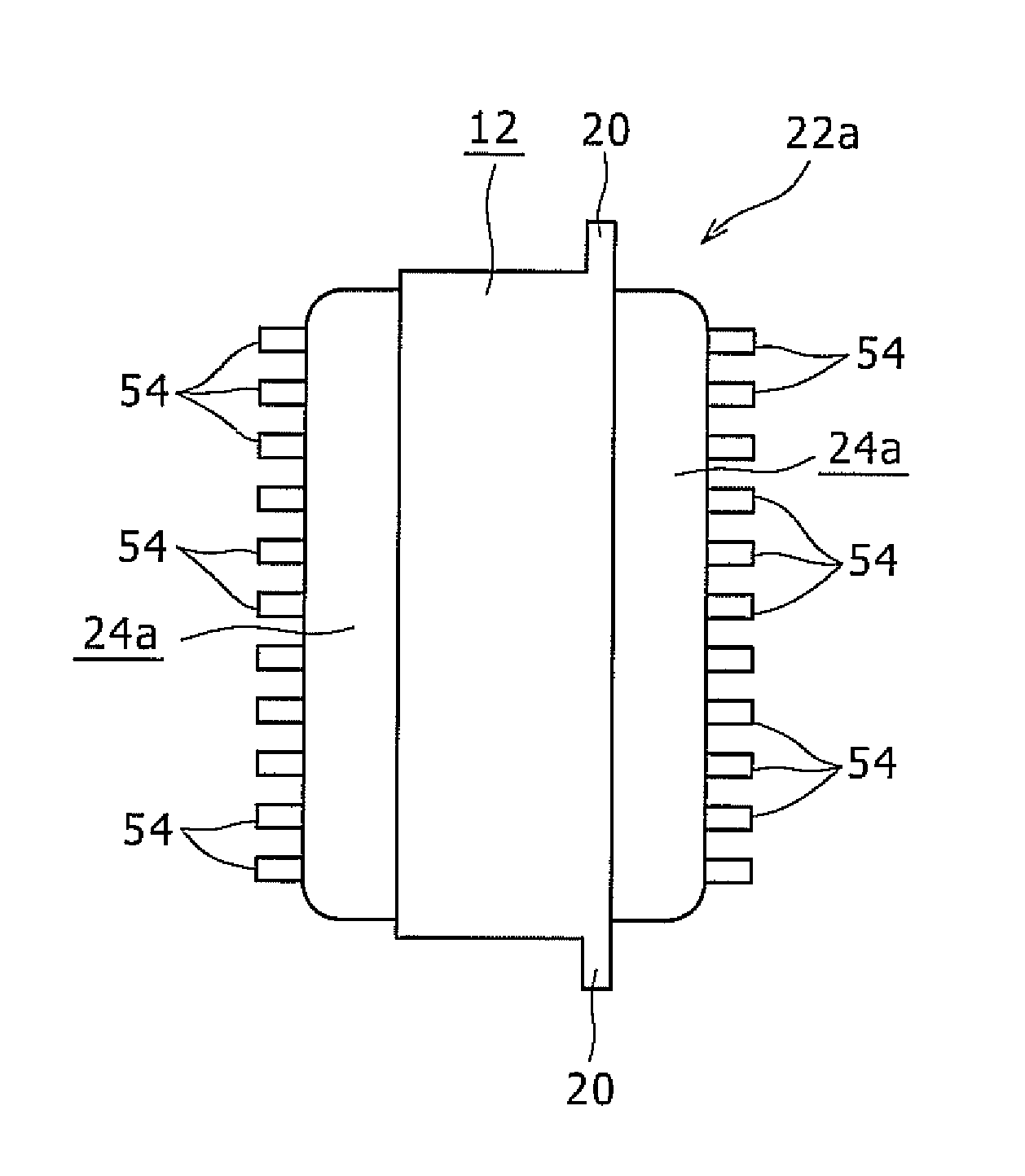
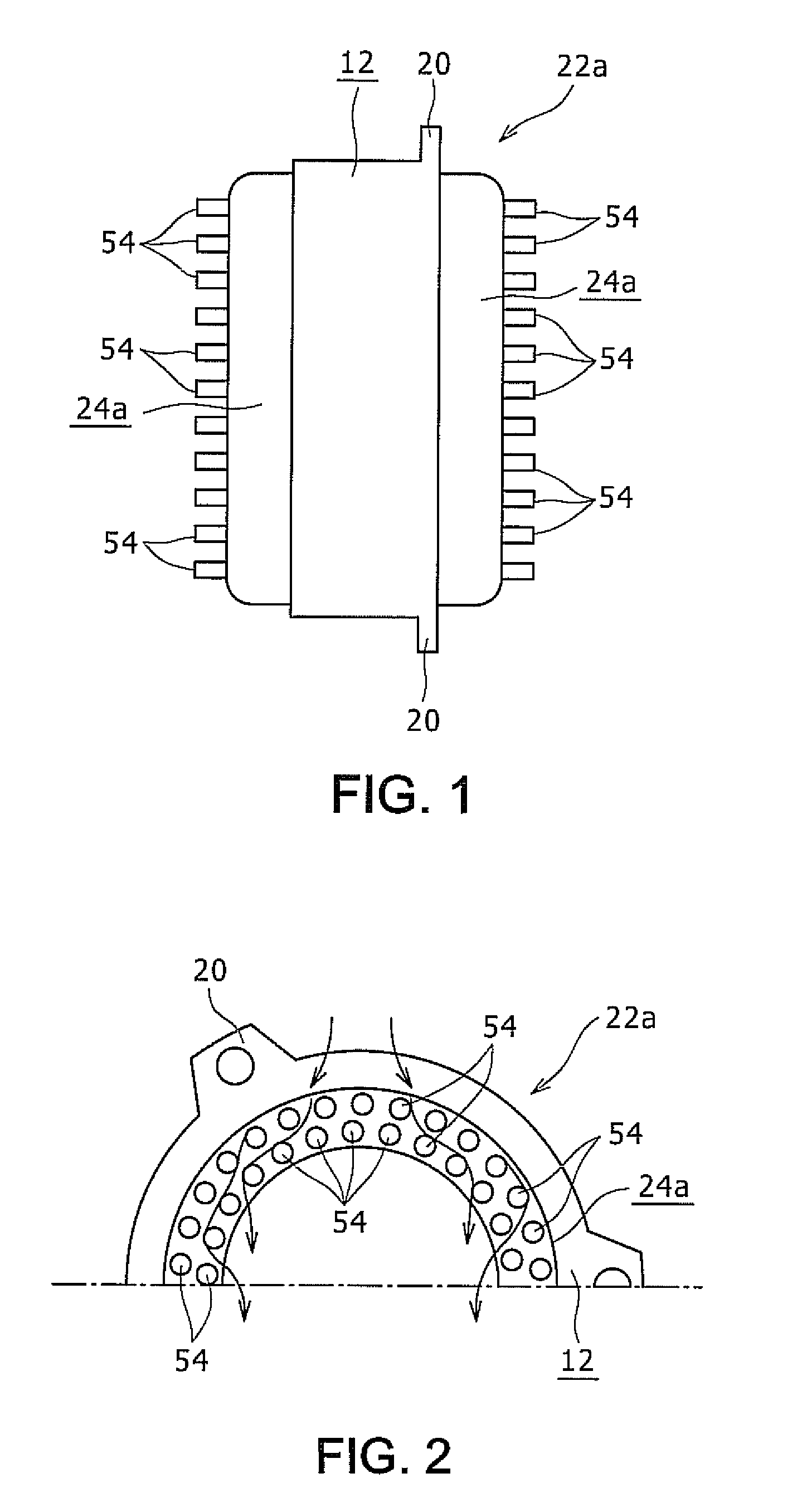
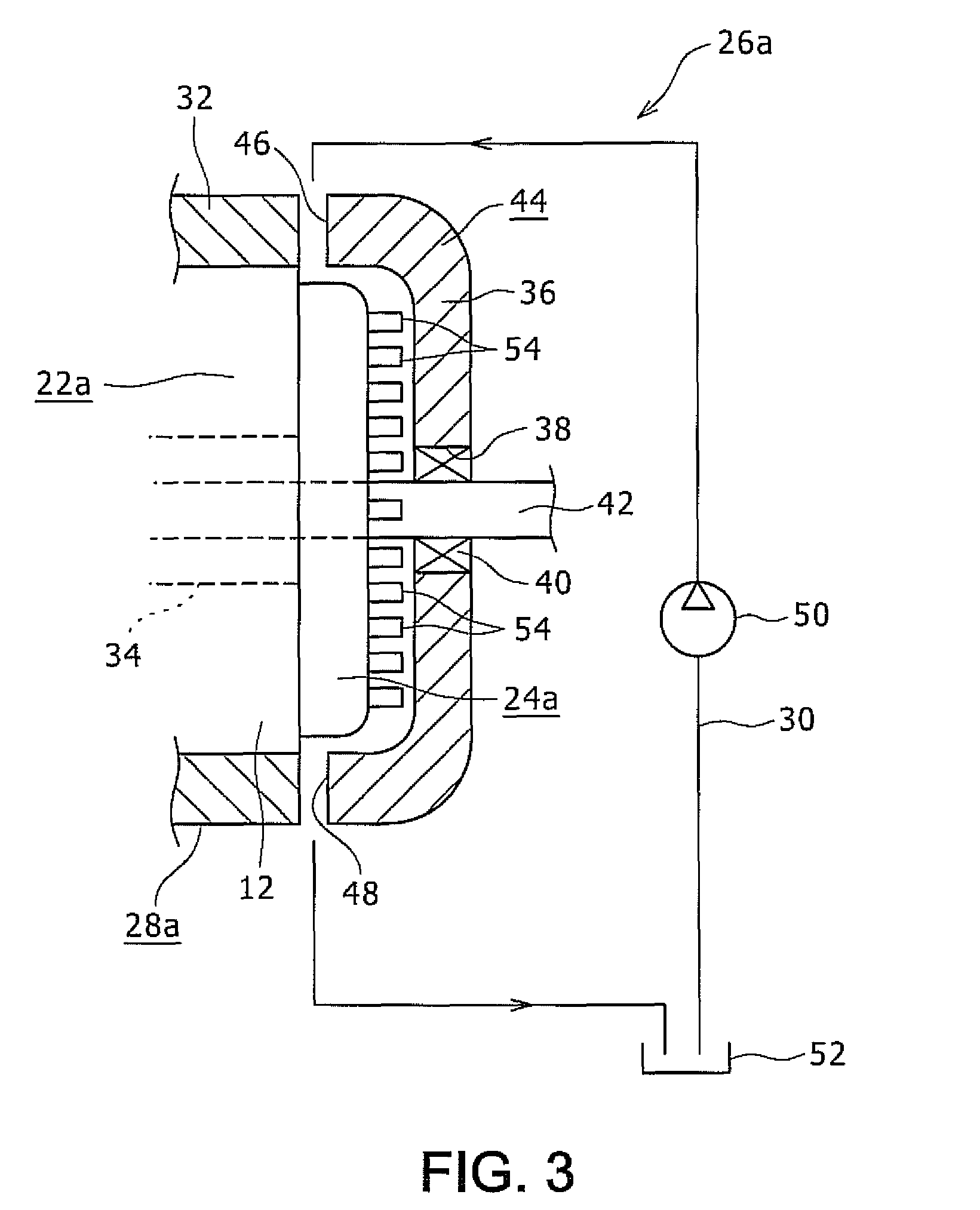
[0046]A first embodiment of the present invention will be described with reference to FIGS. 1, 2, and 3. FIG. 1 is a schematic drawing showing a stator which constitutes a motor as a rotating electric machine according to the first embodiment. FIG. 2 is a drawing showing an upper half portion of the stator shown in FIG. 1 when viewed leftward from the right. FIG. 3 is a perspective view showing a cooling system for the rotating electric machine.
[0047]A motor 28a according to the first embodiment is used to drive, for example, a hybrid vehicle or to generate electricity, and includes a stator 22a shown in FIGS. 1 and 2 and a rotor 34 (see FIG. 3). The stator 22a includes a stator core 12 formed of a laminated steel plate or the like and a pair of resin mold coil ends 24a provided on axial both ends thereof. The stator core 12 is fixed inside a motor case 44 formed of a metal such as aluminum by die casting or the like as shown in FIG. 3. A rotary shaft 42 is disposed radially inside ...
second embodiment
[0059]FIG. 4 is a schematic drawing showing a stator which constitutes a motor as an example of a rotating electric machine according to a second embodiment of the present invention. FIG. 5 is a drawing showing an upper half portion of the stator shown in FIG. 4 when viewed from the right side. In the second embodiment, column-shaped projections 58 of a shaft shape projecting in the radial direction or in a direction inclined with respect to the radial direction are provided on an outer peripheral surface of a resin mold coil end 24b which constitutes a stator 56 at a plurality of positions in the circumferential direction. The column-shaped projections 58 are provided also at positions on the respective resin mold coil ends 24b separated from each other along the radial axis.
[0060]All of the plurality of column-shaped projections 58 positioned within a certain angular range shown by an angle α1 in FIG. 5 with respect to an axial center O (see FIG. 5) of the resin mold coil end 24b ...
third embodiment
[0066]FIG. 6 is a partial cross-sectional drawing showing a motor as an example of a rotating electric machine according to a third embodiment of the present invention. FIG. 7 is a drawing showing an upper half portion of a cover which constitutes the motor shown in FIG. 6 removed from its installation and viewed from the left side in FIG. 6. According to a motor 28b of the third embodiment, in a motor 28 as shown in FIG. 12 which includes the stator 22 conceived in the related art shown in FIGS. 9 to 11, an inner surface portion of a cover 36a which constitutes the motor case 44 opposing the resin mold coil end 24 as the stator coil end is formed of foamed metal 60 as a foamed portion formed from a metal such as aluminum. The foamed metal 60 is provided on an inner peripheral surface of a cylindrical portion 62 which constitutes the bottomed cover 36a and an entire inner surface portion of a bottom panel portion 64 which covers an end portion of the cylindrical portion 62. The cove...
PUM
 Abstract
Description
Claims
Application Information
 - R&D
- Intellectual Property
- Life Sciences
- Materials
- Tech Scout
- Unparalleled Data Quality
- Higher Quality Content
- 60% Fewer Hallucinations
Browse by: Latest US Patents, China's latest patents, Technical Efficacy Thesaurus, Application Domain, Technology Topic, Popular Technical Reports.
© 2025 PatSnap. All rights reserved.Legal|Privacy policy|Modern Slavery Act Transparency Statement|Sitemap|About US| Contact US: help@patsnap.com


