Harvesting energy from vehicular vibrations using piezoelectric devices

a piezoelectric device and vehicular vibration technology, applied in the field of system for generating power, can solve the problems of large effort, vehicle vibration, and undesirable vibrations, and achieve the effect of reducing the number of vibrations, and reducing the frequency of vibrations

Active Publication Date: 2012-03-27
GM GLOBAL TECH OPERATIONS LLC
View PDF94 Cites 40 Cited by
  • Summary
  • Abstract
  • Description
  • Claims
  • Application Information

AI Technical Summary

Problems solved by technology

It is generally known that vehicles are subjected to vibrations, especially while being driven.
These vibrations have typically been considered undesirable.
In fact, a great deal of effort has gone into the development of suspension systems that include springs, dampers, and the like, that provide vehicular stability and insulate the vehicle's passenger compartment from vibration caused by, for example, driving on bumpy or otherwise tortuous roadways.
Currently, the energy associated with these vibrations is lost.

Method used


Image

  • Harvesting energy from vehicular vibrations using piezoelectric devices
  • Harvesting energy from vehicular vibrations using piezoelectric devices
  • Harvesting energy from vehicular vibrations using piezoelectric devices

Examples


first embodiment

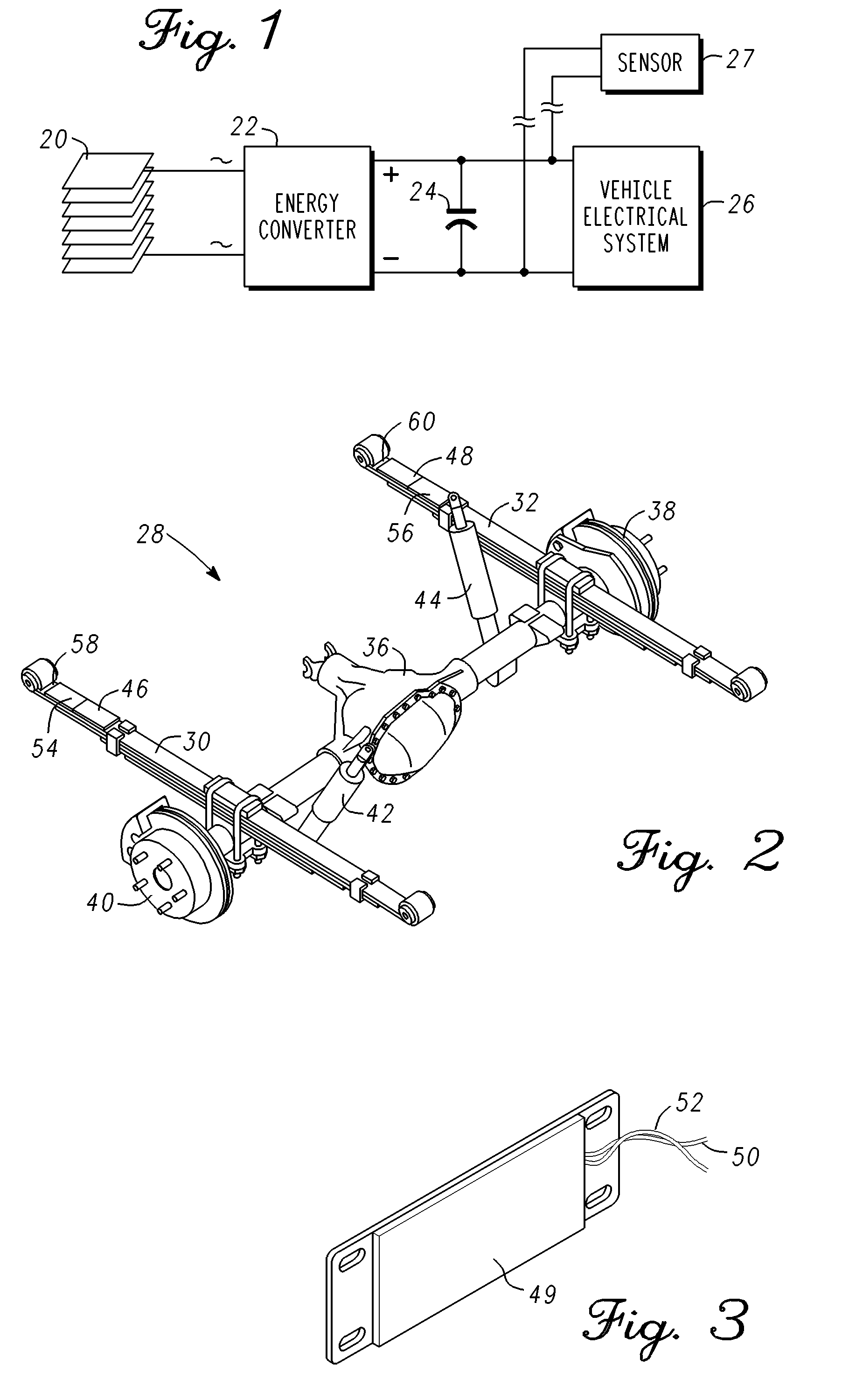
[0023]FIG. 2 is an isometric view of a vehicular spring suspension system 28, in accordance with a As can be seen, leaf spring assemblies 30 and 32 are coupled to an axle / differential housing 36. Individual wheels (not shown) are coupled to rotors 38 and 40 respectively.

[0024]Leaf spring assemblies (30 and 32) are simple forms of springs commonly used for the suspension of wheeled vehicles which, in recent times, are most commonly found on heavy vehicles such as trucks, vans, SUVs, and the like. A leaf spring assembly generally takes the form of a slender, arc-shaped length of steel spring having a generally rectangular cross-section. Attachment means are provided at each end for securing the leaf spring assembly to the vehicle's frame or body. For heavier vehicles, several leaves may be stacked on each other forming several layers typically with progressively shorter leaves. A leaf spring assembly may be attached directly to the frame at both ends, or at one end directly and throu...

fourth embodiment

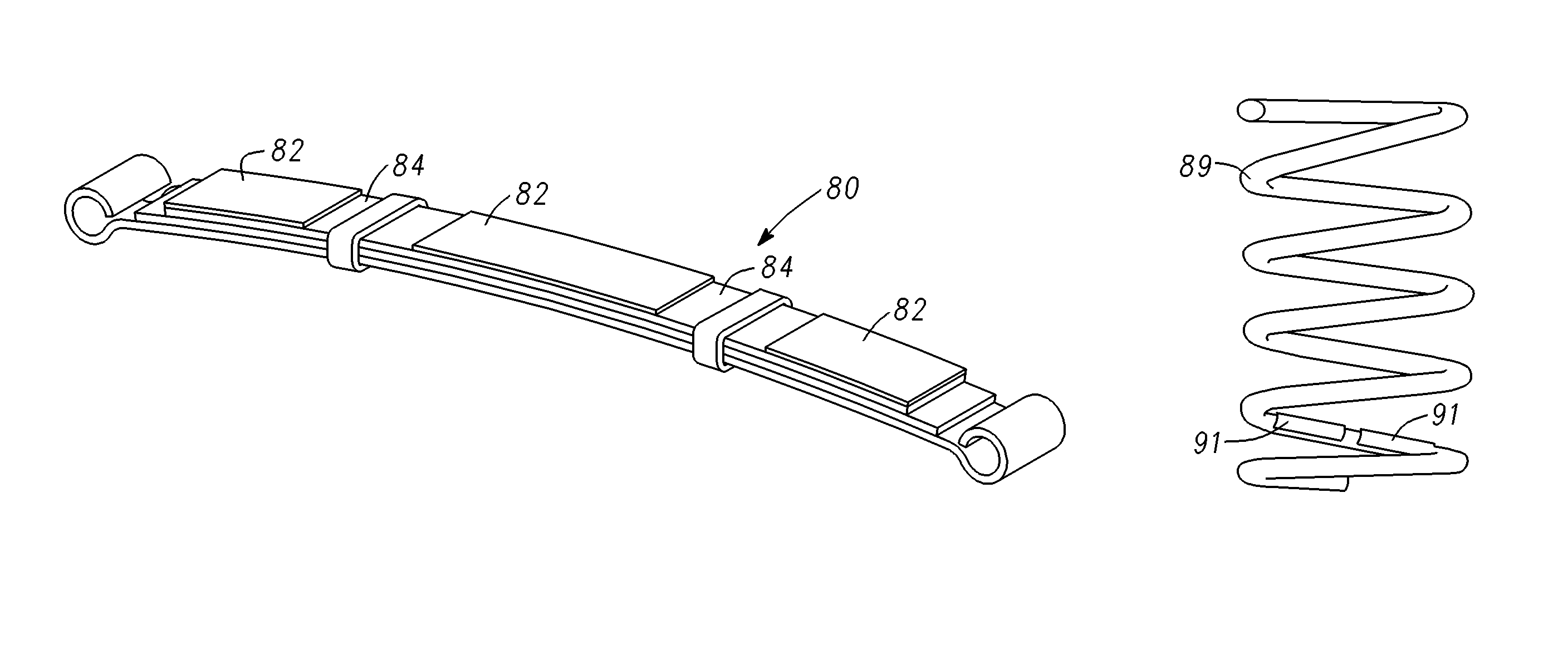
[0028]FIG. 12 is an isometric view of an energy harvesting apparatus in accordance with a fourth embodiment and illustrates some standard components of an automotive coil spring suspension system. First and second hubs 81 and 83 are mounted for rotation on axle assembly 85. Damper assemblies 87 and coil springs 89 are coupled between axle assembly 85 and the vehicle's frame (not shown) in the well known manner to provide a smoother and more stable ride. In this embodiment, flexible piezoelectric composite strips 91 of the type described above are mounted on coil spring 89 as is shown more clearly in FIG. 13. As the coil springs extend and compress during vehicle travel, piezoelectric strips 91 (or a plurality of patches in series or parallel) will deform resulting in a voltage across the piezoelectric device's terminals (e.g. 50 and 52 in FIG. 3). A rectifier 93 may be mounted to the vehicle's structure (e.g. the axle assembly) and coupled to piezoelectric strips 91 to convert the A...

fifth embodiment

[0029]FIG. 14 is an isometric view of an energy harvesting apparatus in accordance with a There is shown in FIG. 14 an automotive suspension that comprises a frame or body side rail 95, a lower control arm 97, and a coil suspension spring 99 coupled between frame 95 and control arm 97. As can be seen, spring 99 is coupled to frame 95 by means of a spring seat 101 having a central protrusion 103 that positions the upper portion of spring 99, and a spring isolator 105 made of a resilient material (e.g. rubber, polyurethane elastomer, etc.) positioned between coil spring 99 and spring seat 101 to avoid contact noise during suspension travel.

[0030]FIGS. 15 and 16 are first and second embodiments of spring isolators 103 and 107, respectively. In each case they comprise an annular portion 109 and a central protrusion 11. Each is provided with a piezoelectric annular disk 112. In FIG. 15, piezoelectric disk 112 is positioned between layers of resilient material 114 and 116. In FIG. 16, a ...


PUM


Abstract

An energy harvesting apparatus for deployment on a vehicle having a frame includes a spring assembly coupled to the frame and configured for compressions and extensions during vehicle travel. A piezoelectric device is mounted on the spring assembly for generating electrical energy in response to the strain imposed thereon. A rectifier is coupled to the piezoelectric device for converting AC electrical energy to DC.

Description

TECHNICAL FIELD[0001]This relates generally to a system for generating power and, more particularly, to a system for harvesting energy from vehicular vibrations utilizing piezoelectric devices.BACKGROUND OF THE INVENTION[0002]Increasing demands for better fuel economy have lead to improvements and developments in hybrid vehicles, electric vehicles, and vehicles powered by fuel cells or diesel fuel. Efforts on the part of the automotive industry to increase fuel economy have included, but are not limited to, reductions in mass, improved aerodynamics, active fuel management, direct injection engines, homogeneous charge compression ignition engines, and hybrid engines. Still, other mechanisms, techniques, and energy sources that will improve fuel economy are continually being sought. To this end, the use of piezoelectric materials to harvest energy has received a great deal of attention in recent years. As is well known, the piezoelectric effect involves the conversion of mechanical st...

Claims


Application Information

Patent Timeline
Patent Type & Authority Patents(United States)
IPC IPC(8): H01L41/107H02N2/18
CPCB60G11/04B60G17/01941F16F1/06F16F1/18H02N2/186B60G2200/314B60G2206/7101B60G2300/60F16F2224/0283
Inventor NAMUDURI, CHANDRA S.LI, YUNJUNTALTY, TIMOTHY J.ELLIOTT, ROBERT B.MCMAHON, NANCY
Owner GM GLOBAL TECH OPERATIONS LLC
Why Eureka
Try Eureka