
Filament lamp and light irradiation heat treatment device

a technology of heat treatment device and filament lamp, which is applied in the direction of immersion heating arrangement, stoves or ranges, furniture, etc., can solve the problems of inability to meet the requirements of such contradictory requirements, the filament lamp cannot be configured with an increased external diameter of the bulb, and the metal foils made wider than before cannot be arranged in the hermetically sealed portions, etc., to achieve the effect of improving the rate of temperature increase of an articl

Active Publication Date: 2012-03-27
USHIO DENKI KK
View PDF20 Cites 0 Cited by
  • Summary
  • Abstract
  • Description
  • Claims
  • Application Information

AI Technical Summary

Benefits of technology

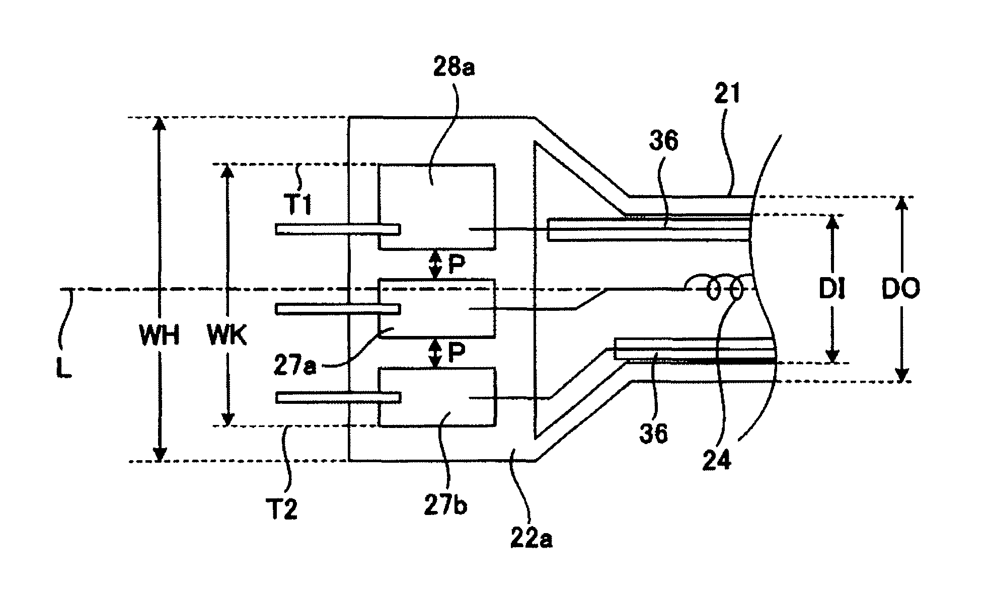
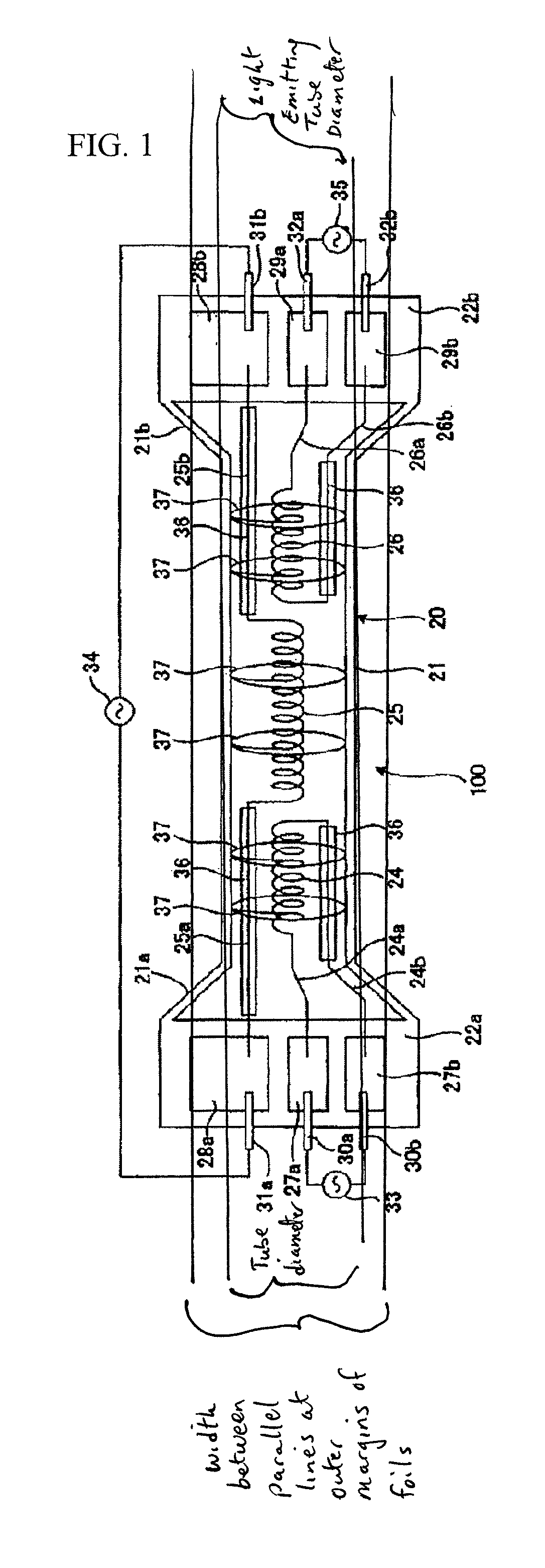
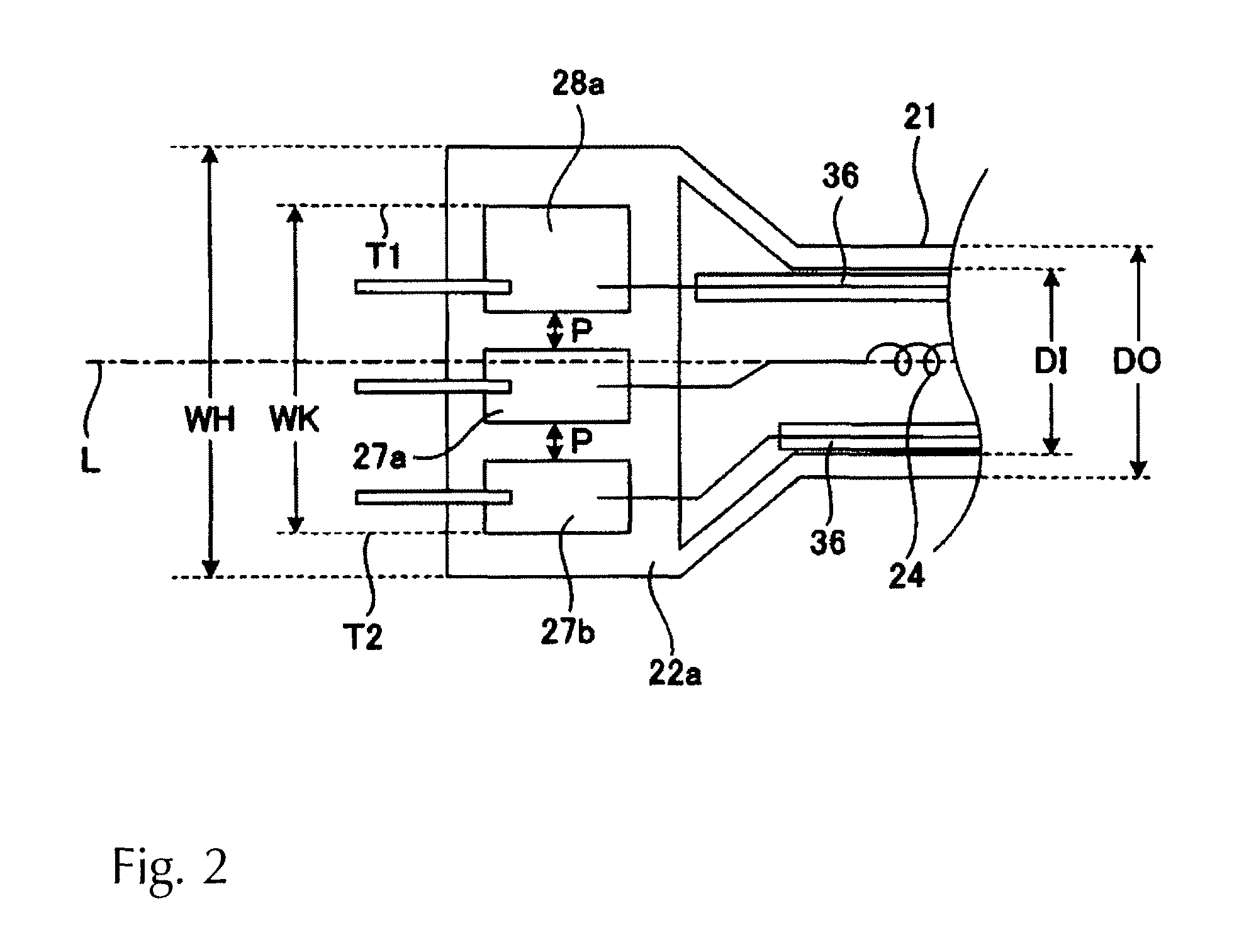
The present invention aims to improve the rate of temperature increase of an article to be treated by widening the width of metal foils embedded in hermetically sealed portions of a filament lamp. This prevents the possibility of meltdown of the metal foils even if the electric current to be supplied to the filament lamps is increased. Additionally, the invention enables secure embedding of metal foils in the hermetically sealed portions even if the external diameter of the bulb of the filament lamp remains the same or is reduced to achieve highly accurate temperature uniformity of the article to be treated. The filament lamp comprises a bulb with a straight tube and a pair of flat hermetically sealed portions continuously formed at both ends of the bulb, where a plurality of coiled filaments are sequentially aligned and arranged in the tube axis direction within the bulb, respectively. The internal leads are connected to the metal foils, respectively, and the external leads are connected to the metal foils, respectively. The hermetically sealed portions are formed wider than the external diameter of the light emitting tube, and the width between the outermost margins of the two metal foils arranged at both ends, between two lines extending in parallel to the tube axis, in a direction at right angles of the tube axis of the bulb, is greater than the internal diameter of the light emitting tube. The light irradiation type heat treatment device of the present invention is characterized by having a lamp unit with a plurality of filament lamps, where flat hermetically sealed portions are arranged in parallel so as to extend in parallel in a direction essentially vertical to an article to be treated, for irradiating light emitted from the lamp unit and heating the article to be treated.

Problems solved by technology

However, in the heat treatment device, since it is necessary to closely align and arrange many filament lamps with respect to the article to be treated in order to realize the highly accurate temperature uniformity of the article to be treated, a configuration with an increased external diameter of the bulb of the filament lamp cannot be adopted.
Therefore, the conventional filament lamp shown in FIG. 8 has the problem that metal foils made wider than before cannot be arranged in the hermetically sealed portions.
Satisfaction of such contradictory requirements is difficult with the conventional filament lamp.

Method used


Image

  • Filament lamp and light irradiation heat treatment device
  • Filament lamp and light irradiation heat treatment device
  • Filament lamp and light irradiation heat treatment device

Examples


example 1

[0042]WK=9 mm[0043]Width of metal foils 28a, 28b=3 mm[0044]Width of metal foils 27a, 27b, 29a, 29b=2 mm[0045]Interval of adjacent metal foils P=1 mm[0046]Maximum rated current of filament 25=12 A[0047]Maximum rated current of filament 24, 26=10 A

example 2

[0048]WK=18 mm[0049]Width of metal foils 28a, 28b=6 mm[0050]Width of metal foils 27a, 27b, 29a, 29b=5 mm[0051]Interval of adjacent metal foils P=1 mm[0052]Maximum rated current of filament 25=20 A[0053]Maximum rated current of filaments 24, 26=16 A

[0054]Thus, since the filament lamp of the present invention improves the rate of temperature increase of an article to be treated, a great current, 10 A to 20 A at maximum, is applied to each filament. Therefore, the metal foils 27a, 27b, 28a, 28b, 29a, 29b are formed to be rather wide so as not to cause meltdown at the time of lighting the filament lamp.

[0055]Further, since this type of filament lamp accurately controls the temperature of the article to be treated, it is preferable to arrange many (at least three) filaments within the light emitting tube 21. In other words, it is assumed that many and wider metal foils are arranged in each hermetically sealed portion; however, as described above, the external diameter of the luminous 21 ...


PUM


Abstract

A filament lamp has a bulb comprised of a straight light emitting tube from which a pair of flat hermetically sealed portions extend, a plurality of coiled filaments arranged within the light emitting tube, in the tube axis direction a pair of internal leads are connected to ends of the filament by a respective one of a plurality of metal foils that are embedded in the hermetically sealed portions, and external leads are connected to the metal foils. The width of metal foils embedded in the hermetically sealed portions is increased so as not to cause them to melt even when an electric current to be supplied to the filament lamp is increased, the hermetically sealed portions being made wider than the external diameter of the light emitting tube and the width between outer margins of the metal foils in a direction at right angles of the tube axis is greater than the internal diameter of the light emitting tube.

Description

BACKGROUND OF THE INVENTION[0001]1. Field of Invention[0002]The present invention relates to a filament lamp and light irradiation heat treatment device, and particularly relates to a filament lamp used for heating an article to be treated and a light irradiation heat treatment device using the filament lamp.[0003]2. Description of Related Art[0004]At present, heat treatment by light irradiation from a light source is used on the occasion of various processes in a semiconductor manufacturing process, for example, film formation, oxidization, nitriding, film stabilization, silicidation, crystallization and ion injection activation. Particularly, rapid thermal processing (RTP) for rapidly increasing or decreasing the temperature of an article to be treated, for example, a semiconductor wafer, is preferably used because it can improve the throughput and quality.[0005]In such a light irradiation type heat treatment device (hereafter, simply referred to as “heat treatment device”) for RT...

Claims


Application Information

Patent Timeline
Patent Type & Authority Patents(United States)
IPC IPC(8): F26B3/30
CPCH01K1/38H01K1/40H01K7/00H01K9/08H05B3/0047H01L21/67115H01L21/324H01L21/00H01K5/02
Inventor MIZUKAWA, YOICHITANINO, KENJI
Owner USHIO DENKI KK
Learn More