Method and apparatus for propagating optical signals along with power feed to illuminators and electrical appliances

a technology of optical signals and power feeds, applied in the direction of television systems, coupling device connections, instruments, etc., can solve the problems of difficult to propagate two-way control signals to leds, no known leds can operate, and connect a separate low voltage control line to an ac powered led illuminator, etc., to achieve low cost and low cost

Active Publication Date: 2012-04-03
ELBEX VIDEO LTD
View PDF15 Cites 87 Cited by
  • Summary
  • Abstract
  • Description
  • Claims
  • Application Information

AI Technical Summary

Benefits of technology

[0006]The transmission of a light, such as a light signal generated by a transmitting LED of a control device, to an LED illuminator via lightguides or optical fibers for switching the illuminator on and off is the main object of the present invention. This includes the simplicity in connecting lightguides to the LED illuminators and their sockets or holders for feeding the simple on-off commands and for more elaborated commands for communicating optical signals comprising visual light, UV or IR signals, thereby introducing new medium for lighting control and communications. The lightguides and the fiber optic cables offer the most efficient communication solutions including the need to insulate the control signals and cables from noises and disturbances within the electrical boxes and system is the other objective.
[0024]The current drain or the on-off state data is sent in response to the received operational command, such as on-off, or in response to an inquiry command (a request for data) on the basis of the current sensor output, thereby providing error free remote controlling of lighting appliances.
[0029]Once the optical signal for illuminators control are becoming common and standard, any future LED illuminator structure, be it illumination panels, or boxes or other structures and assemblies, can all be incorporating a low cost lightguide coupler and be controlled by optical signals of the present invention, providing wholly insulated cables and fire free solutions and provide the basic and the environment for future lighting and electrical appliances control medium, at low cost.

Problems solved by technology

Some very bright LEDs will drain higher current, but none of the known LEDs can operate by applying standard AC power line such as 120 VAC to the LEDs.
The problem facing the present introductions of newly developed LED light devices is the need to integrate the LEDs into existing electrical AC line in apartments, homes, offices and other buildings.
Such one or two way control signals are difficult to propagate to the LEDs via the AC power line, particularly because the DC feed to the LED mandates the introduction of switching power regulators, that are noisy, choppy and disrupt the propagate signals.
On the other hand, connecting a separate low voltage control line to an AC powered LED illuminator is prohibited by the electrical and building codes and therefore cannot be used.
This state is impeding the introduction of LED illuminators with control capabilities and / or limit such introductions to a specialized high priced LED illuminators.

Method used


Image

  • Method and apparatus for propagating optical signals along with power feed to illuminators and electrical appliances
  • Method and apparatus for propagating optical signals along with power feed to illuminators and electrical appliances
  • Method and apparatus for propagating optical signals along with power feed to illuminators and electrical appliances

Examples


Embodiment Construction

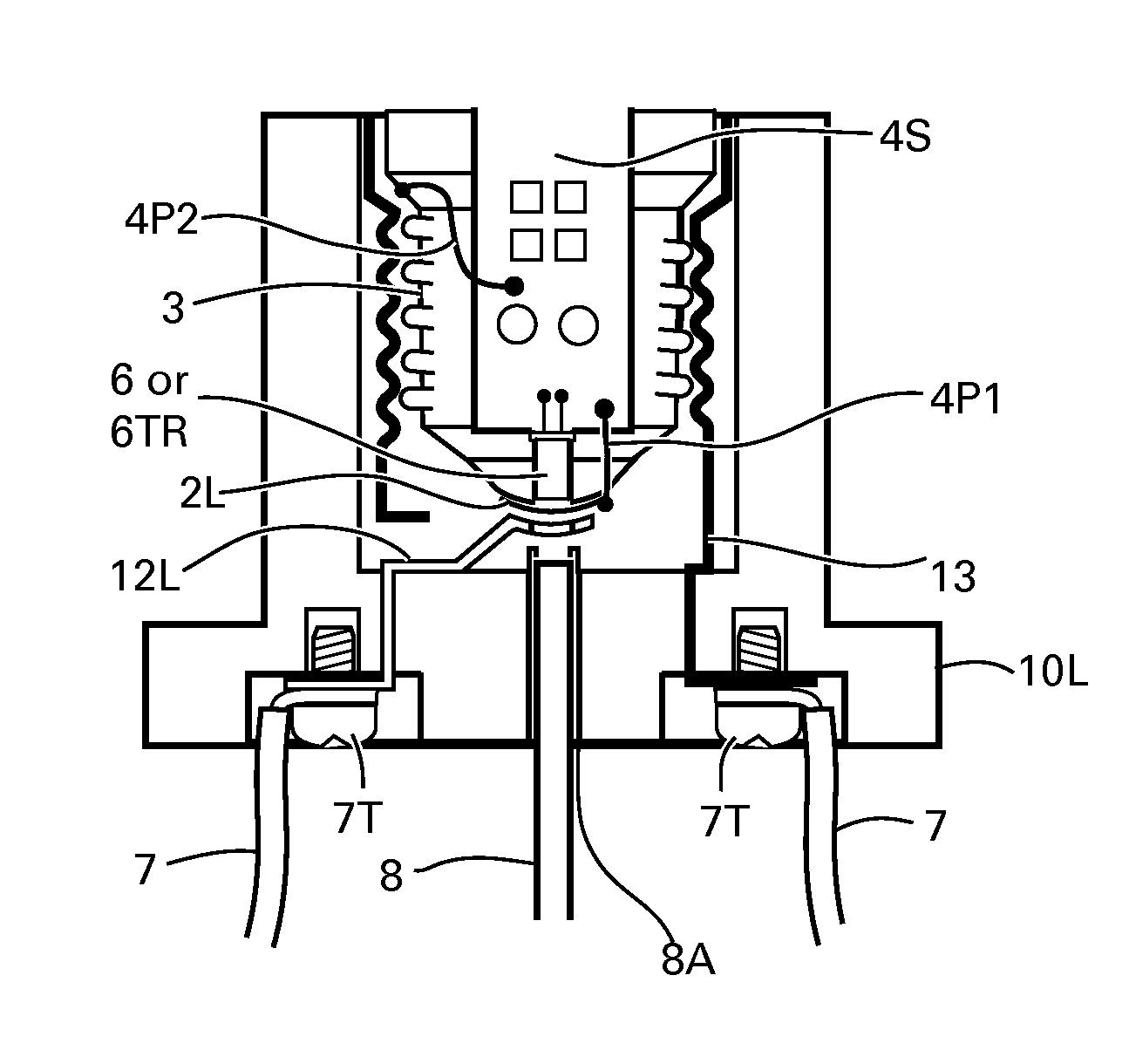
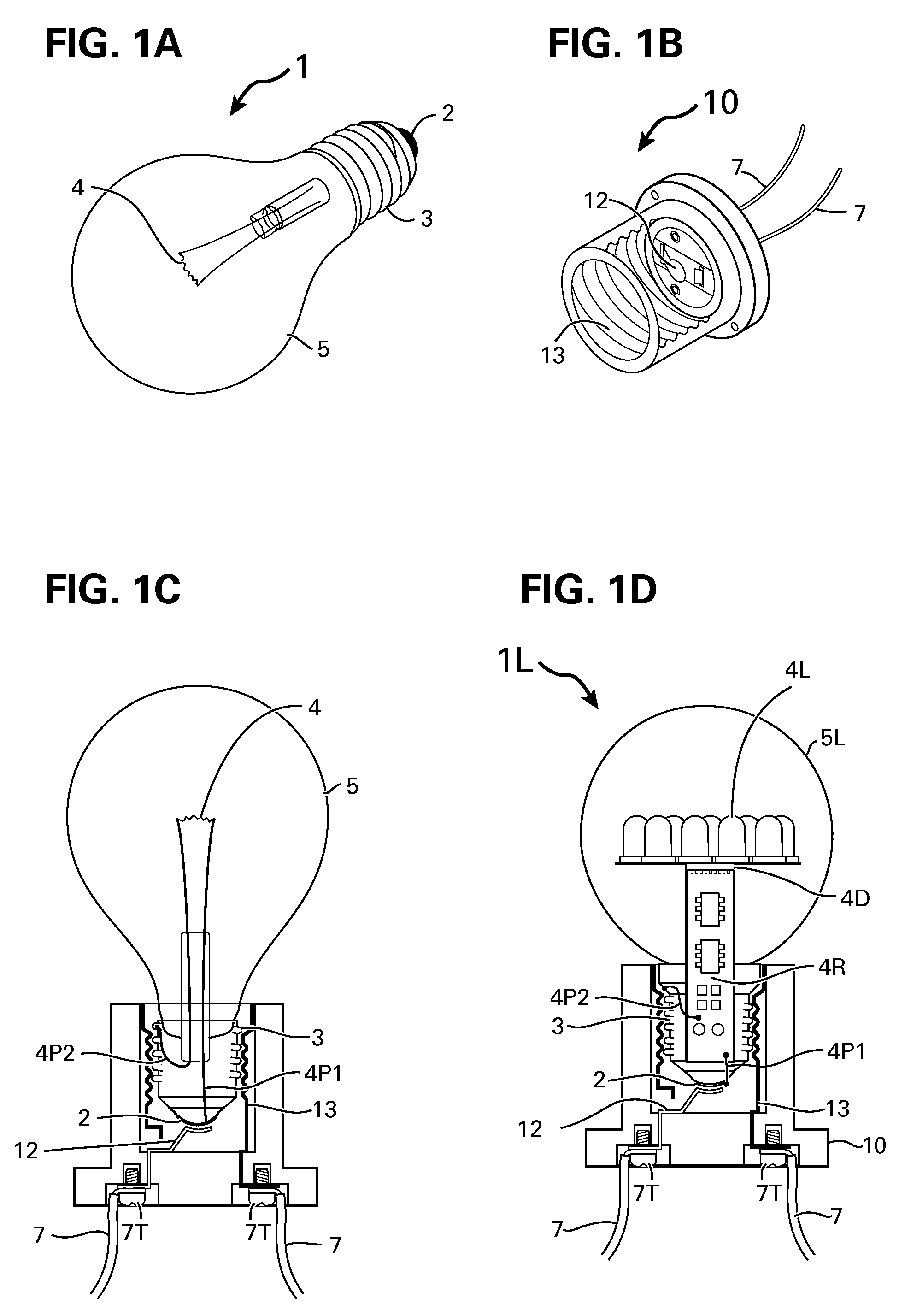
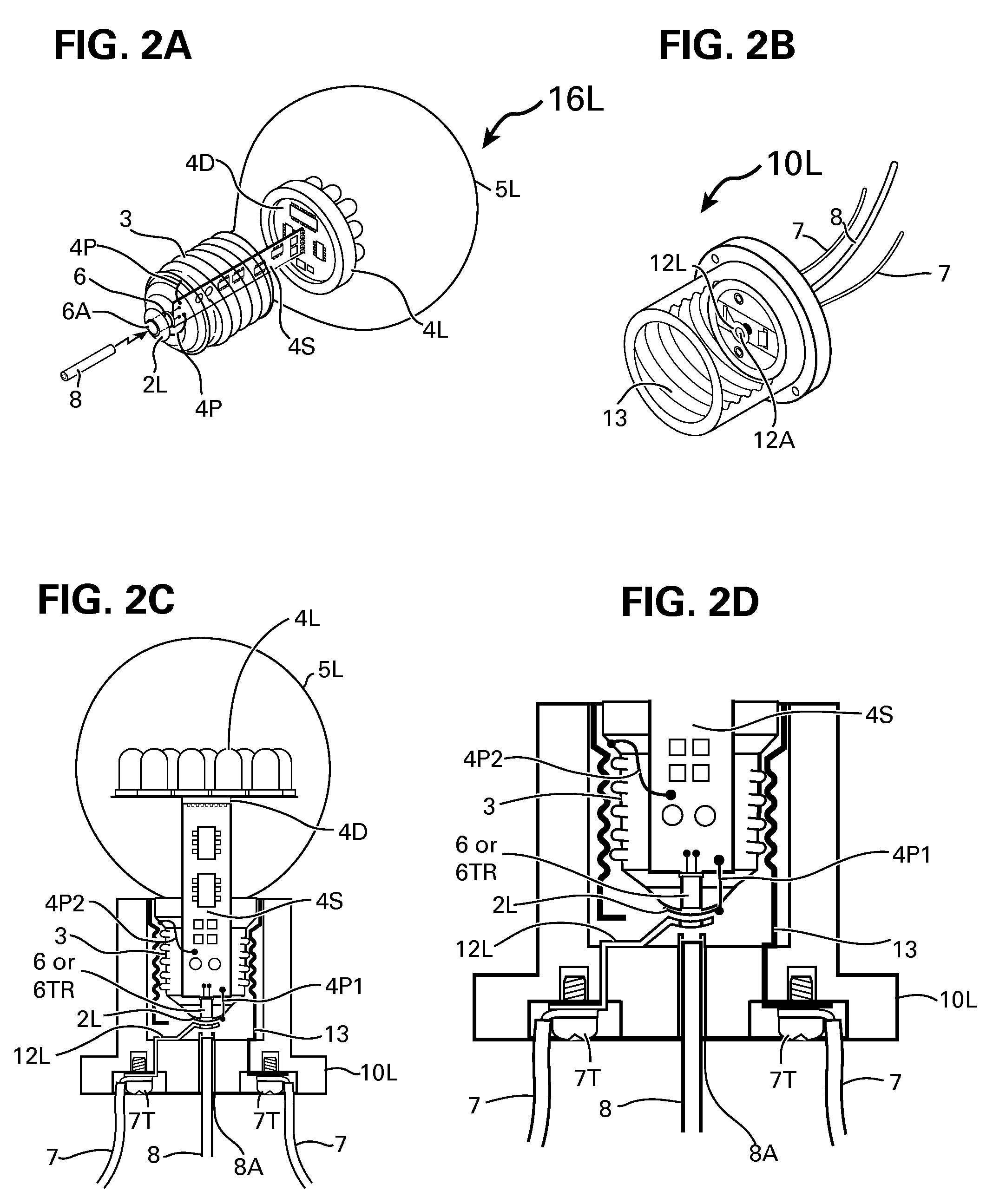
[0048]FIG. 1A shows a typical light bulb 1 comprising the well known screw type base 3 with a rear terminal 2, encapsulated in a glass bulb 5 and a lighting filament 4 connected to its threaded base and rear terminal or contact 2 via internal connections 4P2 and 4P1. FIG. 1B shows a well known socket and holder 10 for the light bulb 1 including the threaded socket 13 and the rear contact 12, both connected to the power wires 7 via the terminals 7T shown in FIG. 1C.

[0049]The attaching of the bulb 1 to its socket and holder 10 is processed by the well known screw-in action or the rotating of the bulb clockwise into the socket 13 until the rear terminal or the rear surface 2 touches the contact 12 inside the socket 10. As shown in the sectional drawing of FIG. 1C the inner structure of the threaded socket 13 and the rear terminal 12 are such that it will be literally impossible to add terminals for connecting a separate control line to the LED illuminator 1L that is constructed into a ...


PUM

PropertyMeasurementUnit
voltagesaaaaaaaaaa
wavelengthaaaaaaaaaa
diameteraaaaaaaaaa

Abstract

In a method and apparatus for propagating optical signals via optical cables such as plastic optical fiber, known as lightguide joint and mingled with the electrical wiring and home automation system for controlling LED illuminators enclosed in standard screw type bulb bases or plug-in bases, such as used for halogen lamp via optical signal propagated through such standard bases. Same optical signals are propagated through power outlets and via power cable assemblies to electrical appliances for controlling the appliances operation and on-off switching. Full range of control, distribution, signal conversion, keypads and touch screen including video interphones monitors and shopping terminals operate and controls such home automation via the optical cables.

Description

FIELD OF INVENTION[0001]LED illuminators including AC powered LED illuminator, other AC or DC powered appliances, electrical outlets, lightguide and fiber optic cables, light and home automation controllers, switches and signal distributors.BACKGROUND OF THE INVENTION[0002]LED illuminators are operating on low voltages of 2V˜5V with a given current drain such as 20 mA˜50 mA. Some very bright LEDs will drain higher current, but none of the known LEDs can operate by applying standard AC power line such as 120 VAC to the LEDs. To connect an LED illuminator directly to an AC power line, the power must be rectified and regulated to within the LED operating voltage and current levels.[0003]The problem facing the present introductions of newly developed LED light devices is the need to integrate the LEDs into existing electrical AC line in apartments, homes, offices and other buildings. LED illuminators can be controlled in many ways, such as changing their light color, hue and brightness....

Claims


Application Information

Patent Timeline
Patent Type & Authority Patents(United States)
IPC IPC(8): H05B37/00G02B6/36
CPCG08C23/06H05B37/0254H04N7/186Y10T29/49117H01R33/22H05B47/18H04N7/00
Inventor ELBERBAUM, DAVID
Owner ELBEX VIDEO LTD
Why Eureka
Try Eureka