Method and arrangement for the contactless inspection of moving electrically conductive substances

a technology of moving electrically conductive substances and contactless inspection, which is applied in the direction of magnetic measurements, devices using electric/magnetic means, instruments, etc., can solve the problems of not allowing the measurement of flow velocity of very slowly flowing or very weak electrically conductive substances, and the measurement accuracy of the system is greatly limited, so as to achieve high measurement precision and sensitivity, and easy implementation.

Inactive Publication Date: 2012-04-03
TECH UNIV ILMENAU
View PDF30 Cites 5 Cited by
  • Summary
  • Abstract
  • Description
  • Claims
  • Application Information

AI Technical Summary

Benefits of technology

[0008]Thus, the basic problem of the present invention is to furnish a method and arrangement for the contactless measurement of attributes influencing the electrical conductivity, such as flow velocity and volume flow for electrically conducting substances, which on the one hand allow very high measurement precision and sensitivity. Furthermore, it should be easy to implement such a method. The corresponding arrangement should be economical in construction and easily convertible. Furthermore, it should be possible to determine the spatial distribution of the various properties, such as flow velocity and conductivity in the substance, and also to determine the contour of the gutter (or the like) where the flow is occurring.

Problems solved by technology

However, these already known measurement methods have three serious drawbacks.
First, due to their limited sensitivity, they do not allow measuring flow velocities in very slowly flowing or very weak electrically conductive substances, such as glass melts.
Second, the measurement accuracy of the systems is greatly limited in an electromagnetically perturbed environment, since the magnetic field sensors will be affected by even the slightest parasitic fluctuations of the magnetic field, due to their small spatial dimension.
Third, the measurement sensitivity of the method, being characterized by the ratio between secondary field and primary field, cannot be increased by heightening the primary field.
Despite their advantages over the first mentioned methods, the force-measuring systems are of little or no use for a number of important special problems, including flow measurement.
Such a system is very heavy, it requires an elaborate current supply, and can only be transported to a different place of use after costly disassembly of the measurement system.
These local sensors are not suited to determining the mass flow or the volume flow, because the magnetic field generated by them only penetrates part of the cross section through which the conductive substance is flowing.
Furthermore, the measurement sensitivity of the local sensors declines with the third power (or even the fourth in the case of greater distances) of the distance from the conductive substance and is therefore not adequate for many application instances.

Method used


Image

  • Method and arrangement for the contactless inspection of moving electrically conductive substances
  • Method and arrangement for the contactless inspection of moving electrically conductive substances
  • Method and arrangement for the contactless inspection of moving electrically conductive substances

Examples


second embodiment

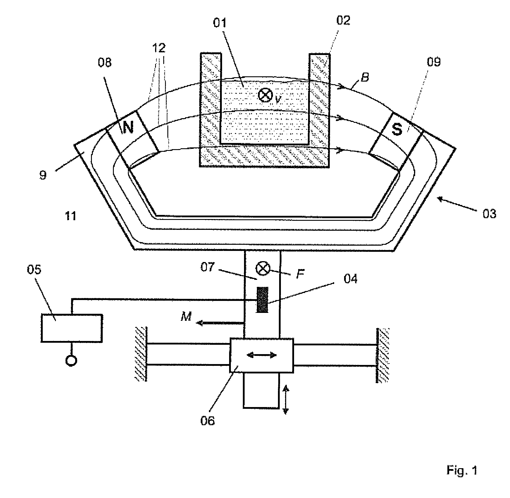
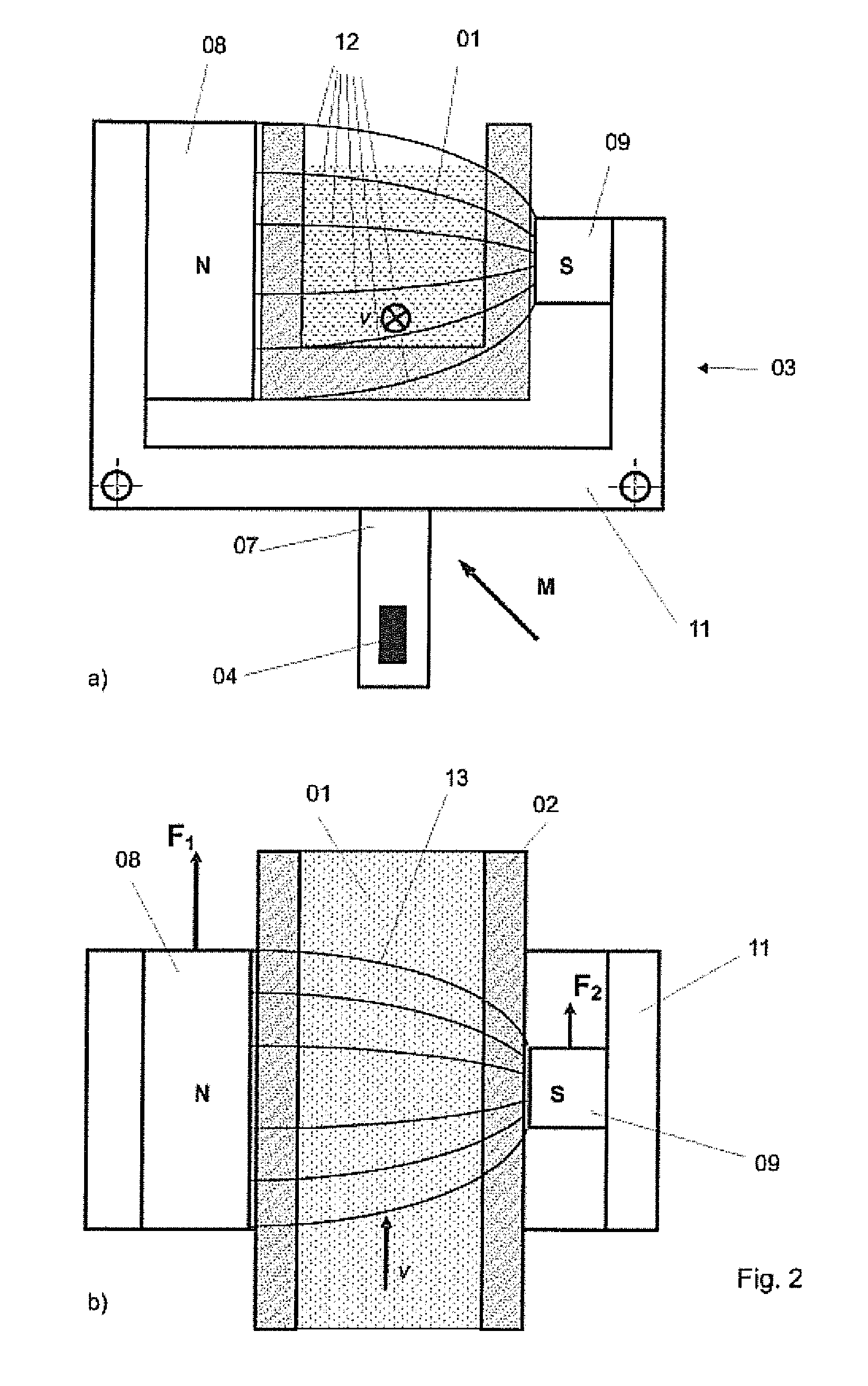
[0054]FIG. 2 shows a Lorentz force anemometer. In this embodiment, the magnetic system 03 is asymmetrical and so the primary field B has an inhomogeneous configuration. The oppositely placed permanent magnets 08, 09 have different sizes and / or different magnetization strengths. The inhomogeneous design of the magnetic field B has the advantage that all components of the force F and the torque M acting on the magnetic system 03 (i.e., all state parameters) are different from zero, thereby achieving maximum information about the substance 01.

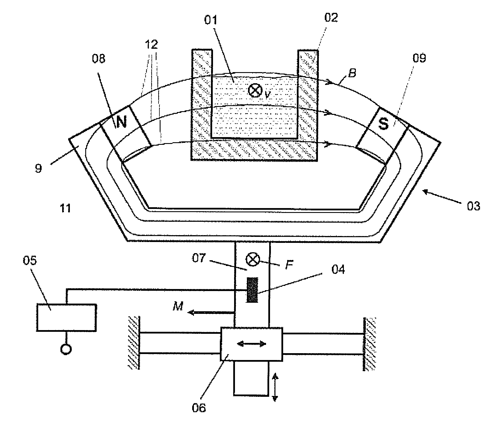
[0055]This circumstance is illustrated in part a of FIG. 2 by representing the directional vector of the torque M acting on the magnetic system 03. In contrast to this, the vertical force component in the system shown in FIG. 1, for example, is equal to zero because of the left / right symmetry and does not contribute to the information obtained.

[0056]Part b of FIG. 2 shows a plan view of the Lorentz force anemometer of the second embodiment. One re...

third embodiment

[0057]FIG. 3 shows, in the invented Lorentz force anemometer, a magnetic system 03 with inhomogeneous primary magnetic field B in exploratory mode. Parts a and b of the figure show different positions of the magnetic system 03 relative to the substance 01, part c shows a plan view of part a. The magnetic system 03 has two poles, consisting of permanent magnets 08, 09, which are arranged with a horizontal offset relative to each other and magnetically joined together by the yoke 11. This produces an inhomogeneous primary field B, which is shown by the field lines 12 drawn. The overall magnetic system 03 can be moved vertically by means of the actuator system 06, not shown. The yoke 11 is at least partly enclosed by a coil 13. The strength of the primary field B created by the permanent magnets 08, 09 and the coil 13 is varied by the size of the current flow in the coil 13.

[0058]The magnetic system 03 shown in FIG. 3 has two actuating variables for the exploratory mode, namely, the ve...

fourth embodiment

[0063]FIG. 4 shows the Lorentz force anemometer with a rotating primary field B. The magnetic system 03 in this case comprises two oppositely placed disks 14 of magnetically conductive material, joined together, which form the yoke, in which a plurality of permanent magnets 08, 09 with alternating polarity are embedded or glued on (FIG. 4b and c).

[0064]This disks 14 are arranged opposite each other so that each time one magnetic north pole of a permanent magnet 08 lies opposite a magnetic south pole of a permanent magnet 09.

[0065]In the exploratory mode, the magnetic system 03 is placed in rotation by the Lorentz force generated by the moving substance 01 and the rotary speed ω is measured continually by means of a tachometer 15. From the measured speed ω, the evaluation unit 05 calculates the sought property of the substance 01, such as the flow rate.

[0066]It also within the scope of the invention to install a motor with integrated torque measuring system, instead of the tachometer...


PUM

PropertyMeasurementUnit
conductanceaaaaaaaaaa
magnetic fieldaaaaaaaaaa
magnetic systemaaaaaaaaaa

Abstract

The invention relates to a method and arrangement for the contactless determination of conductivity-influencing properties and their spatial distribution over the entire cross section of an electrically conductive substance moving in a primary magnetic field (B). The substance may be a liquid or a solid. A simultaneous measurement of a number of mechanical state parameters of the magnetic system is performed (three-dimensional components of the force and the torque), said parameters being variable by the effect of a secondary field on the magnetic system, the secondary field being produced on the basis of eddy currents induced in the substance by the primary field (B). To determine the spatial distribution of the property that is sought, the primary field is changed in intensity or form a number of times and a measurement of the state parameters is carried out for each change. The determination of the properties sought or their distribution takes place by solving an inverse problem using the method of least squares.

Description

FIELD OF THE INVENTION[0001]The invention concerns a method and arrangement for the contactless determination of properties of electrically conductive moving substances, which can be solid or liquid. In the preferred case of the investigation of liquid substances, these are viewed as a moving substance during flow through a pipe, channel, or similar guiding device. The invention also concerns a method and arrangement for the contactless determination of the spatial distribution of the properties of such substances, such as the flow velocity and electrical conductivity of the substance. The invention can be used in particular for measuring flow and flow volume in metallurgy, but it is also suitable for tasks in nondestructive materials inspection. The arrangement according to the invention shall also be called hereafter a Lorentz force anemometer.BACKGROUND OF THE INVENTION[0002]The precise measurement of flow velocities, flow volumes, and other properties which affect the electrical...

Claims


Application Information

Patent Timeline
Patent Type & Authority Patents(United States)
IPC IPC(8): G01N27/72G01R33/12
CPCG01F1/56G01N27/9026
Inventor THESS, ANDREKOLESNIKOV, YURIKARCHER, CHRISTIAN
Owner TECH UNIV ILMENAU
Why Eureka
Try Eureka