Method for determining the rotational axis and the center of rotation of a vehicle wheel

a technology of vehicle wheels and rotational axes, which is applied in the direction of instruments, measurement devices, computing, etc., can solve the problems that affect the accuracy of measurement, and achieve the effect of removing the

Active Publication Date: 2012-04-03
BEISSBARTH AUTOMOTIVE TESTING SOLUTIONS GMBH
View PDF11 Cites 7 Cited by
  • Summary
  • Abstract
  • Description
  • Claims
  • Application Information

AI Technical Summary

Benefits of technology

[0011]With these measures, any effects of influencing variables on the measured results that arise from the actual conditions that may occur during actual driving on an actual, is uneven road are largely eliminated, thereby resulting in increased measuring accuracy and more reliable measurement results.
[0013]The main advantages of the present invention are that it allows for a precise determination of the rotation axis and center of rotation of a wheel during travel on a real road. The use of additional mechanical devices is therefore avoided, e.g., roller sets or counterrotating slide plates for rotating the wheel while the vehicle is at a standstill, for use to determine the rim runout compensation as a correction factor for the alignment measurement.
[0015]Current requirements on the evenness of a wheel alignment station may therefore be reduced considerably, thereby making it possible to perform a measurement on a normal workshop floor or a good road surface.
[0019]It is possible to eliminate faulty effects of influencing quantities when the correction factors or compensating functions that are ascertained are roll angle data determined via the difference in the trajectory of the body features of the left and right sides of the vehicle.
[0023]According to further advantageous measures for eliminating the effects of undesired influencing quantities on the measured results, additional correction data or correction functions are used that account for the dependence of the toe and camber on the spring deflection state and the steering angle.

Problems solved by technology

In closer examinations, the inventor determined that uneven features of actual roads and actual vehicle motions may significantly affect the accuracy of the measurement in the determination of the axis of rotation and center of rotation of vehicle wheels.

Method used


Image

  • Method for determining the rotational axis and the center of rotation of a vehicle wheel
  • Method for determining the rotational axis and the center of rotation of a vehicle wheel
  • Method for determining the rotational axis and the center of rotation of a vehicle wheel

Examples


Embodiment Construction

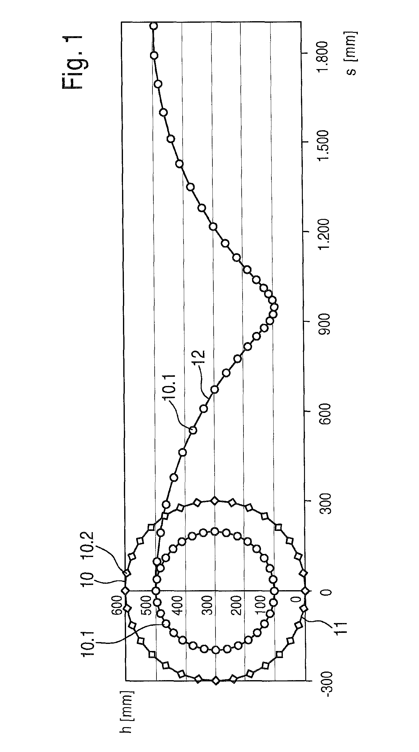
[0034]FIG. 1 shows, in the left half of the illustration, the trajectory of two wheel features 10, i.e., an inner wheel feature 10.1 close to a center of rotation, and an outer wheel feature 10.2 close to the outer circumference, both of which are located at a level h above rolling path s. When the wheel performs a rotating motion with the vehicle at a standstill (e.g., with the vehicle raised), trajectories 11 are circular trajectories. FIG. 1 also shows trajectory 12 of inner wheel feature 10.1 while the vehicle is moving and the wheel is therefore rotating. Trajectory 12 is a cycloid, assuming that the motor vehicle travels along a straight line on an ideal plane. To record trajectories 11 and 12, it is possible to use the measuring devices with the optical recording devices described in greater detail in the publications mentioned initially, in which case time-synchronized images are captured from different perspectives. FIG. 2 shows the coordinates of four wheel features 10.1 i...


PUM


Abstract

The invention relates to a method for determining the rotational axis and the rotating center of a vehicle wheel by means of at least two image capture units assigned to each other in position and situation during the journey of the vehicle, and by means of an analysis unit arranged downstream of said units, processing the recorded image information, taking into account multiple wheel features (10) present on the wheel or attached for the measurement, and by means of at least one bodywork feature present on the bodywork or attached for the measurement, wherein 2D-coordinates of the wheel features (10) and of the at least one bodywork feature are synchronously detected, and from these the 3D-coordinates of the features are calculated at certain time intervals and counted back to a previously established reference time point or corresponding reference position of the vehicle wheel, taking into account the distance traveled by the at least one bodywork feature relative to the reference position. To achieve measurement results that are as error free as possible, especially also when traveling on a real driving surface, it is provided that the paths of the wheel features (10) and of the at least one bodywork feature in the evaluation undergo an analysis with respect to the effects of at least one of the influencing variables, steering lock angle, steering motion, driving surface unevenness, and change of speed, and that from the analysis, correction factors or compensation functions are obtained for correcting the effects.

Description

CROSS-REFERENCE[0001]The invention described and claimed hereinbelow is also described in PCT / EP2007 / 0656621, filed on Jul. 1, 2007 and DE 10 2006 035 924.0, filed on Jul. 31, 2006. This German Patent Application, whose subject matter is incorporated here by reference, provides the basis for a claim of priority of invention under 35 U.S.C. 119 (a)-(d).BACKGROUND OF THE INVENTION[0002]The present invention relates to a method for determining the geometric position of the rotational axis and the center of rotation of a vehicle wheel in a measurement station coordinate system, while the motor vehicle is being driven, by using at least two optical recording devices assigned to each other in terms of position, and by using a downstream evaluation unit that processes the image information that was captured, with consideration for several wheel features present on the wheel or attached for measurement purposes, and by using at least one body feature present on the body or attached for meas...

Claims


Application Information

Patent Timeline
Patent Type & Authority Patents(United States)
IPC IPC(8): G06K9/00
CPCG01B11/2755G01B2210/14G01B2210/20G01B2210/30
Inventor NOBIS, GUENTERABRAHAM, STEFFENUFFENKAMP, VOLKER
Owner BEISSBARTH AUTOMOTIVE TESTING SOLUTIONS GMBH
Why Eureka
Try Eureka