Method and device for rock drilling

a rock drilling and rock technology, applied in the direction of boring/drilling equipment, drilling machines and methods, percussive tools, etc., can solve the problems of limited control of the shape of the shockwave and limitation of the shockwave length

Inactive Publication Date: 2012-04-10
ATLAS COPCO ROCK DRILLS
View PDF14 Cites 6 Cited by
  • Summary
  • Abstract
  • Description
  • Claims
  • Application Information

AI Technical Summary

Benefits of technology

[0005]It is an aim of the present invention to provide a method and a device as indicated above, that provide developments and enhancements in respect of previously known pulse machines, and particularly give the possibility of enhanced shockwave shape control. In particular it is an aim to be able to produce more effective shockwave pulses for the particular application.
[0007]The invention provides good possibilities of controlling the length of the shockwave pulse whereby are achieved a number of important advantages. There is thus, in the case of rock drilling, possible to drill with a rock drilling efficiency which is regulated in the direction of an enhancement. For other types of pulse machines it is also essentially a question of providing a more efficient working process.
[0010]This way of adjust the forces to each other i.a. has the advantages that no pulses are induced until the machine is pressed-on with the feed force, since the impulse piston without (or with a low) feed force in a so called initial portion is pressed against a stop that is arranged inside the machine housing. Idle strikes are thereby effectively avoided which could otherwise be harmful for the machine and, for example, affect a drill string negatively and in particular induce loosening of threads in the drill string.
[0012]The factors that affect the resistance against rock penetration are parameters such as rock hardness and size of the drill bit and in particular the area of the hard metal buttons at the front of the drill bit that strikes against the rock. The resistance against rock penetration thus increases with increased rock hardness as well as with increased drill bit size.
[0020]The invention also allows the possibility of achieving simplified damping such that shockwave reflexes are received by elements providing said second force.
[0022]The invention allows the parameters to be set such that the impulse piston during drilling is controlled in the direction of a “floating position”, wherein it will not come into contact with metal surfaces in either tool direction or in the opposite direction, but instead is “supported” by fluid on its both sides, which leads to reduced noise and reduced wear.

Problems solved by technology

In convention rock drilling with rock drill machines including percussive pistons there are limited possibilities of controlling the shape of the shockwave.
Thereafter the force is released onto the impulse piston (by releasing the impulse piston), the latter is displaced forwardly, normally until it reaches a mechanical stop, which results in limitation of the shockwave length.

Method used


Image

  • Method and device for rock drilling
  • Method and device for rock drilling
  • Method and device for rock drilling

Examples


Embodiment Construction

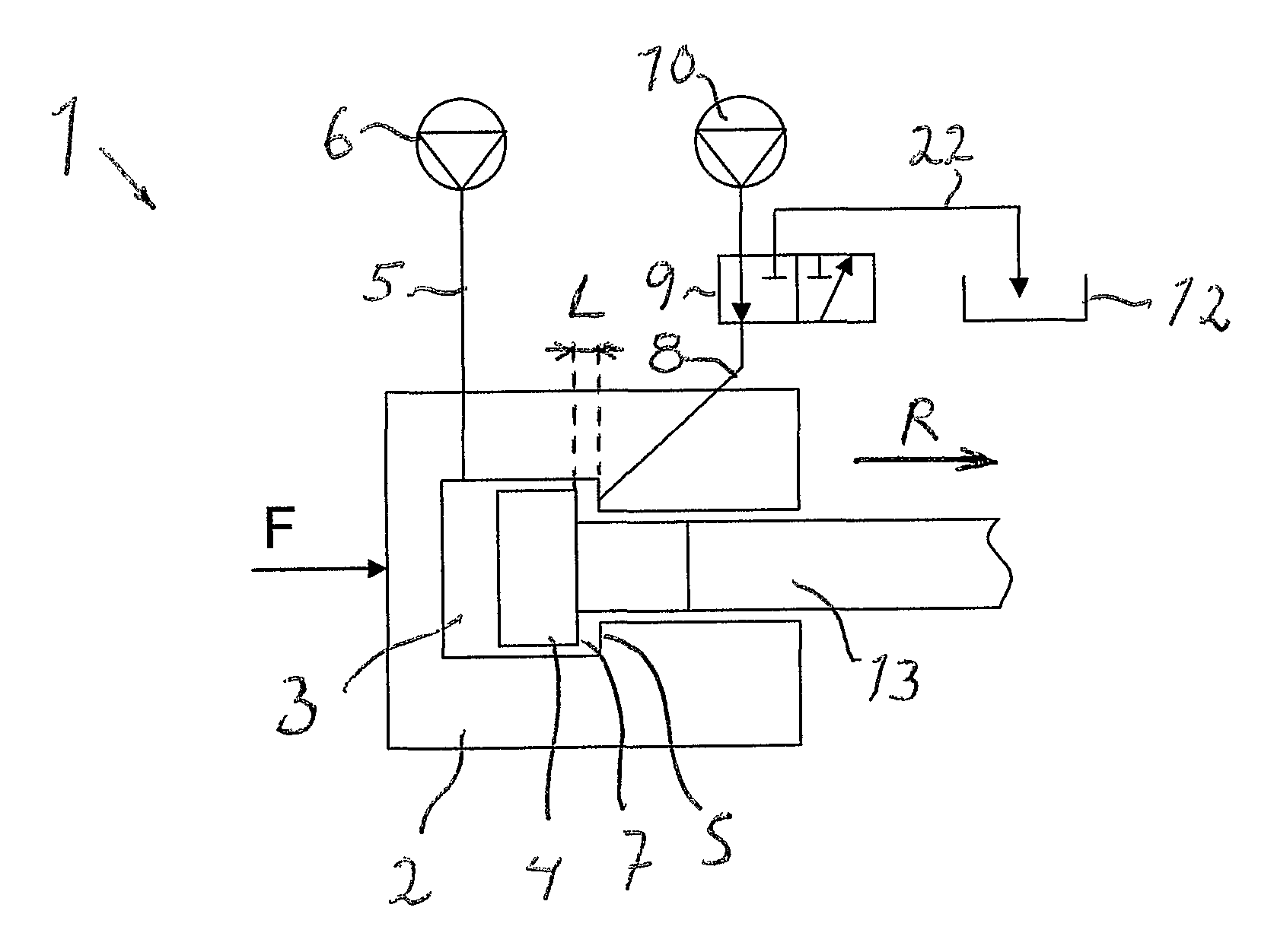
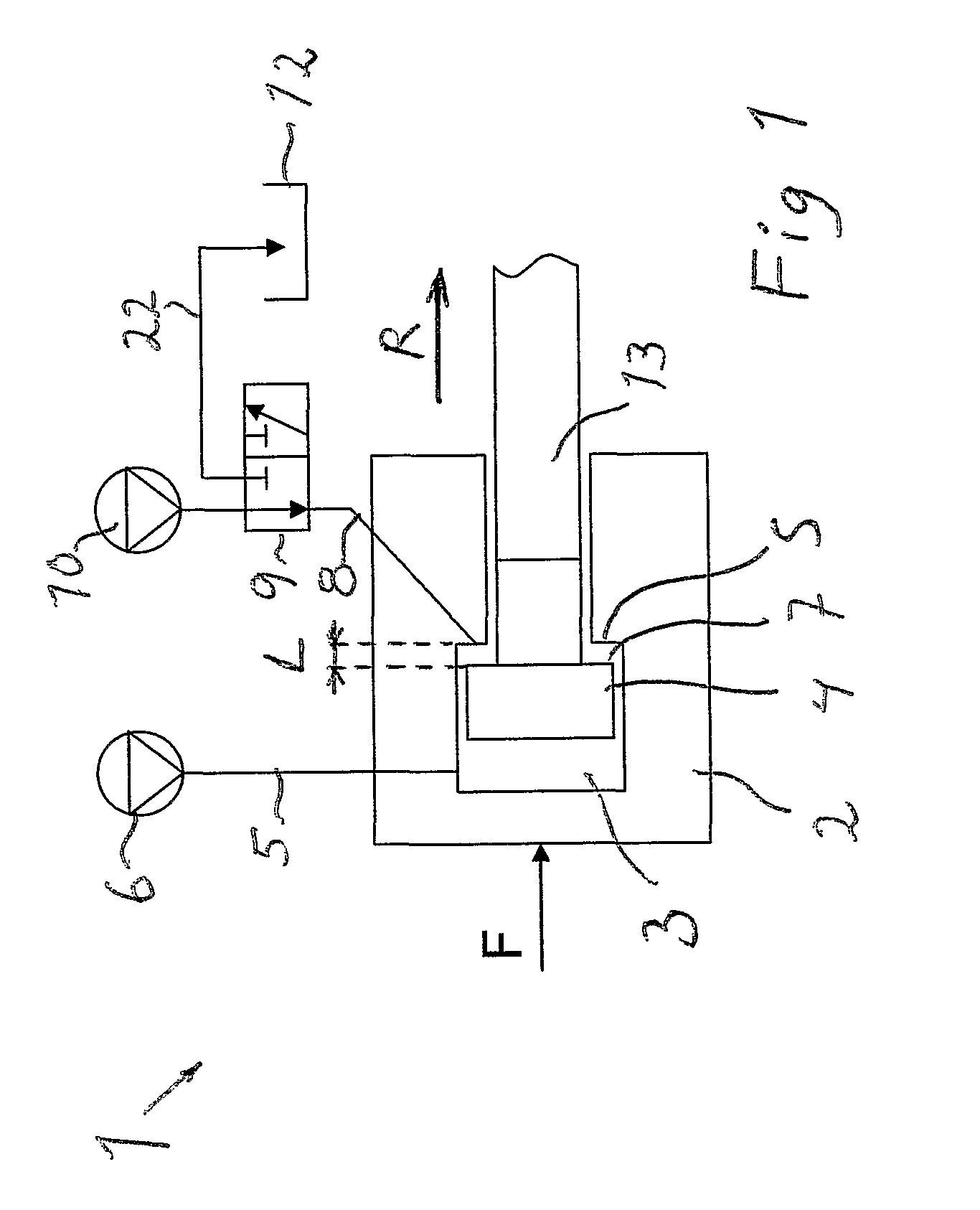
[0030]A pulse drilling machine according to the invention which is generally indicated with 1, includes a housing 2, wherein an impulse piston 4 is reciprocally moveable in a limited manner. The impulse piston lies over an interface against an upper portion of a drill string indicated with 13. Adjoining to the lower side of the impulse piston 4 is arranged a first chamber 7, which can be pressured with a first pressure P1 affecting the impulse piston with a first force in a direction opposite to a tool direction R. The pressure in the first chamber 7 is controlled in that a valve 9 periodically transmits exit pressure from a pump 10 to this chamber 7 over a pressure conduit 8. From the valve also leads a tank conduit 22 to the tank 12 for periodic relief of the first chamber 7.

[0031]Adjoining to the second side of the impulse piston 4 is arranged a second chamber 3 which can be pressurized with a second pressure P2 for producing a second force acting in the tool direction R.

[0032]In...


PUM

PropertyMeasurementUnit
pressureaaaaaaaaaa
lengthaaaaaaaaaa
forceaaaaaaaaaa

Abstract

A method for producing Shockwave pulses in a tool direction (R) of a pulse machine (1) having a housing (2), wherein an impulse piston (4) is arranged, wherein the impulse piston is influenced by a first force in a direction opposite to said tool direction through a first fluid pressure (Pi) in a first chamber (7), and by a second force in said tool direction, wherein 'a Shockwave pulse is produced through a rapid relief of the first fluid pressure after displacement of the impulse piston (4) relative to the housing in a direction opposite to the tool direction, is distinguished in that the length of the shock wave is controlled by the length (L) of said displacement is regulated. The invention also concerns a device, rock drilling machine and a rock drilling rig.

Description

FIELD OF THE INVENTION[0001]The invention concerns a method for producing shockwave pulses. The invention also concerns a device for producing shockwave pulses. Further the invention concerns a rock drilling machine including such a device and a drill rig.BACKGROUND OF THE INVENTION[0002]During rock drilling, shockwave pulses are generated in the form of pressure force pulses, which are transmitted from a shockwave creating device, such as a percussion device, through a drill string all the way to a drill bit. The buttons of the drill bit are thereby pressed with high intensity against the rock and accomplishes crushing and forming of crevices in the meeting rock.[0003]In conventional rock drill machines shockwave pulses are generated by a percussive piston, which strikes against a drill shank for further transfer of the shockwave to the drill string. In convention rock drilling with rock drill machines including percussive pistons there are limited possibilities of controlling the ...

Claims


Application Information

Patent Timeline
Patent Type & Authority Patents(United States)
IPC IPC(8): E21B7/18
CPCB25D9/145B25D2250/221B25D9/14E21B44/00
Inventor TUOMAS, GORAN
Owner ATLAS COPCO ROCK DRILLS
Why Eureka
Try Eureka