
Catalyst for treating exhaust gas and device for treating exhaust gas using the same

a catalyst and exhaust gas technology, applied in the field of exhaust gas catalysts, can solve the problems of slow gas diffusion in exhaust gas, often found incomplete etc., and achieve the effects of improving the gas diffusibility of exhaust gas, improving the treatment of exhaust gas, and improving the treatment effect of exhaust gas

Inactive Publication Date: 2012-04-10
JOHNSON MATTHEY PLC
View PDF49 Cites 14 Cited by
  • Summary
  • Abstract
  • Description
  • Claims
  • Application Information

AI Technical Summary

Benefits of technology

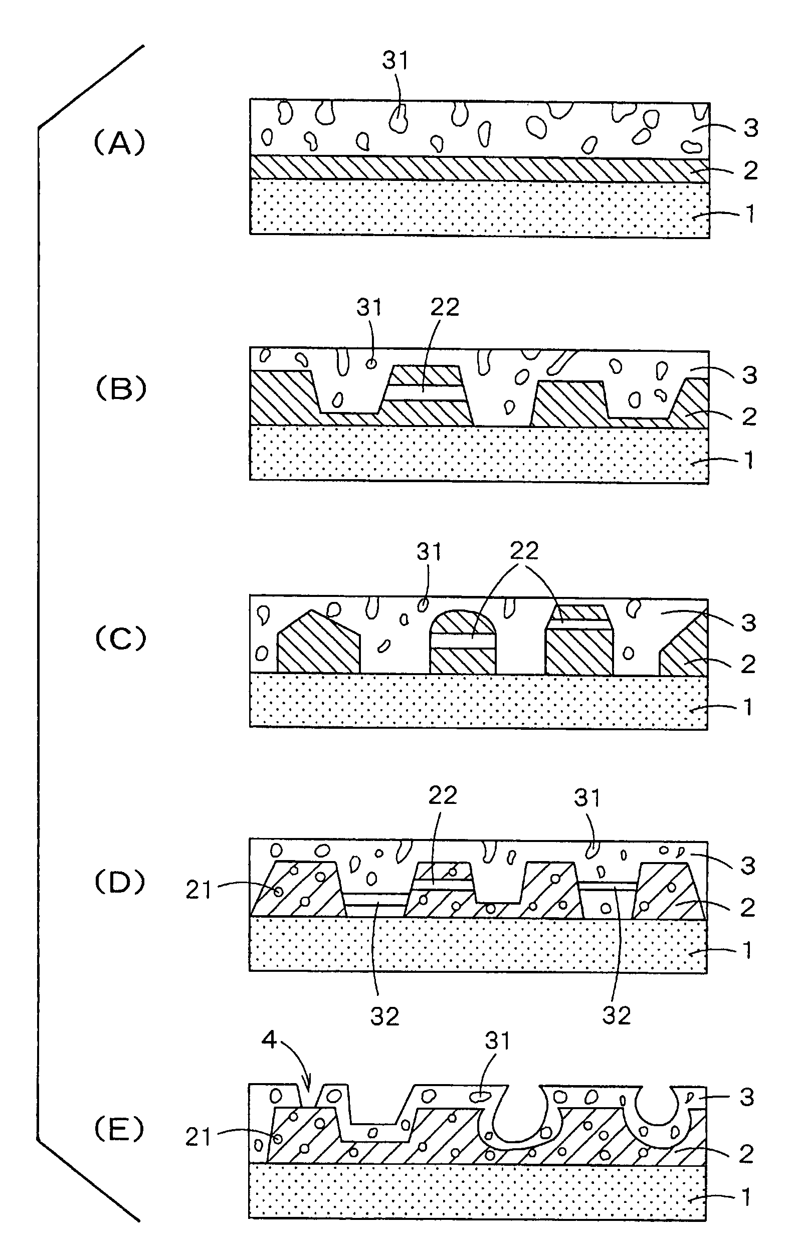
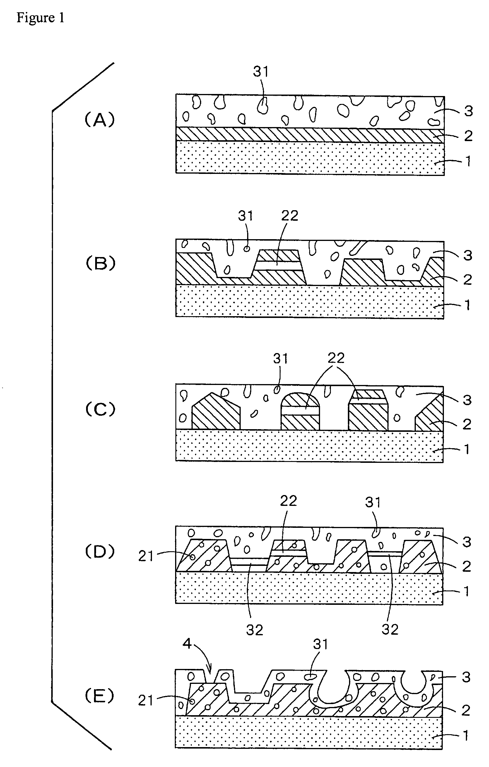
[0009]In devising the invention, the inventors discovered the constitution of an exhaust gas catalyst that improved the treatment of exhaust gas. In particular, they found that the treatment of exhaust gas could be improved by means of a catalyst formed from a plurality of layers wherein at least one of the plurality of layers contained voids of specified minor axis and diameter and comprised catalyst components. The invention is accordingly based on these findings. The invention aims thereby to provide an exhaust gas catalyst that raises the gas diffusibility of the exhaust gas, enabling treatment of the exhaust gas to be improved.

Problems solved by technology

In nearly all existing exhaust gas catalysts, however, the catalyst components are formed uniformly on the support; gas diffusion in the exhaust gas is therefore slow when the exhaust gas flows into the exhaust gas catalyst, and as a result the exhaust gas is often found to be incompletely treated.

Method used


Image

  • Catalyst for treating exhaust gas and device for treating exhaust gas using the same
  • Catalyst for treating exhaust gas and device for treating exhaust gas using the same
  • Catalyst for treating exhaust gas and device for treating exhaust gas using the same

Examples


example 1

[0058]γ-Al2O3 powder 25 parts by weight, water 60 parts by weight and platinum nitrate solution were mixed and an acrylic resin [a resin of mean diameter ca. 30 μm to ca. 150 μm (on average ca. 60 μm) was used] was further mixed therewith as forming agent to constitute 10 wt % of the total. A slurry wherein the forming agent was uniformly dispersed was obtained by agitating for 30 min in an air atmosphere with a high speed mixer (Silverson Machines Inc.). A cordierite honeycomb substrate (volume 1000 cc, 600 cells / in2: NGK Insulators Ltd.) was prepared, dipped in the aforesaid slurry, and withdrawn; after excess slurry had been blown off, the support was calcined for 1 hour at 500° C. in air to lay down a first layer.

[0059]γ-Al2O3 powder 5 parts by weight, water 20 parts by weight and rhodium nitrate solution were mixed and an acrylic resin [a resin of mean diameter ca. 0.5 μm to ca. 100 μm (on average ca. 20 μm) was used] was further mixed therewith as forming agent to constitute 2...

example 2

[0061]An exhaust gas catalyst was obtained as in Example 1 except that the second layer was formed without addition of forming agent.

example 3

[0062]An exhaust gas catalyst was obtained as in Example 1 except that the first layer was formed without addition of forming agent.


PUM

PropertyMeasurementUnit
porosityaaaaaaaaaa
porosityaaaaaaaaaa
diameteraaaaaaaaaa

Abstract

A catalyst for treating an exhaust gas has at least a carrier and plural layers formed on the carrier, wherein at least one layer of the above plural layers has an interstice in the layer, and at least one layer of the above plural layers contains a catalyst component. The above catalyst for treating an exhaust gas allows the enhancement of the diffusion of an exhaust gas in a catalyst layer, which results in the improvement of catalyst efficiency.

Description

[0001]This application is the U.S. National Phase application of PCT International Application No. PCT / JP2004 / 016230, filed Nov. 1, 2004, and claims priority of Japanese Patent Application No. 2004-301597, filed Oct. 15, 2004.FIELD OF ART[0002]The invention relates to an exhaust gas catalyst wherein a plurality of layers has been formed on a support.BACKGROUND ART[0003]The following may be listed as specific examples of exhaust gas catalysts for internal combustion engines and automotive engines in particular: oxidation catalysts for simultaneously treating hydrocarbon (HC) and carbon monoxide (CO) in exhaust gas; three-way catalysts for simultaneously treating the hydrocarbon, carbon monoxide and nitrogen oxides (NOx) in exhaust gas; NOx occlusion-reduction catalysts, wherein NOx is occluded from the exhaust gas at lean air-fuel ratio, the air-fuel ratio is switched to the theoretical air-fuel ratio or a rich air-fuel ratio before the occluded NOx reaches saturation, and the NOx is...

Claims


Application Information

Patent Timeline
Patent Type & Authority Patents(United States)
IPC IPC(8): B01J23/00B01J21/00B01J20/00
CPCB01D53/945B01J23/40B01J23/63B01J35/10B01J37/0018B01J37/0219B01J37/0234B01J37/0244F01N3/28B01J23/42B01J23/464Y02T10/22Y02T10/12
Inventor CHO, JINTANIKAWA, KENJI
Owner JOHNSON MATTHEY PLC
Learn More