Magnetic head-positioning servo system, magnetic head test system and magnetic disk test system

a servo system and magnetic head technology, applied in the direction of maintaining the alignment of the head carrier, functional testing of the recording head, instruments, etc., can solve the problems of reducing the resonance frequency of the actuator, and reducing the positioning accuracy of the magnetic head, so as to achieve high positioning accuracy and increase the displacement

Inactive Publication Date: 2012-04-10
HITACHI HIGH-TECH CORP
View PDF7 Cites 0 Cited by
  • Summary
  • Abstract
  • Description
  • Claims
  • Application Information

AI Technical Summary

Benefits of technology

[0006]For example, there is a case where one actuator is used to let the magnetic head mounted on the HGA to follow the target track. In this case, when the eccentricity of the target track is large, it is necessary to increase the displacement of the actuator to move the HGA, requiring an actuator with a large generating displacement. However, there is a problem that the positioning accuracy decreases. The actuator with a large generating displacement can obtain a large displacement with reduced spring-rigidity to support the moving part, resulting in a decrease in the resonance frequency of the actuator. The servo band width of the positioning servo system is reduced, leading to a problem of a decrease in the positioning-accuracy of the magnetic head.
[0009]According to a feature of the present invention, it is possible to realize a head-positioning servo system with increased displacement and high positioning-accuracy.
[0010]Further, it is also possible to provide a magnetic head test system and magnetic disk test system capable of performing a test of a magnetic disk with large eccentricity of a target track, as well as a test of a magnetic head using a magnetic disk with large eccentricity of a target track in an accurate manner.

Problems solved by technology

One is that the center of the target track once written to the magnetic disk is displaced from the rotation center due to assemblage error and the like occurring in attachment and detachment of the magnetic disk to and from the spindle.
However, there is a problem that the positioning accuracy decreases.
The actuator with a large generating displacement can obtain a large displacement with reduced spring-rigidity to support the moving part, resulting in a decrease in the resonance frequency of the actuator.
The servo band width of the positioning servo system is reduced, leading to a problem of a decrease in the positioning-accuracy of the magnetic head.
This generates large vibration due to the driving reaction force, leading to a problem that the positioning-accuracy of the magnetic head is degraded.

Method used


Image

  • Magnetic head-positioning servo system, magnetic head test system and magnetic disk test system
  • Magnetic head-positioning servo system, magnetic head test system and magnetic disk test system
  • Magnetic head-positioning servo system, magnetic head test system and magnetic disk test system

Examples


first embodiment

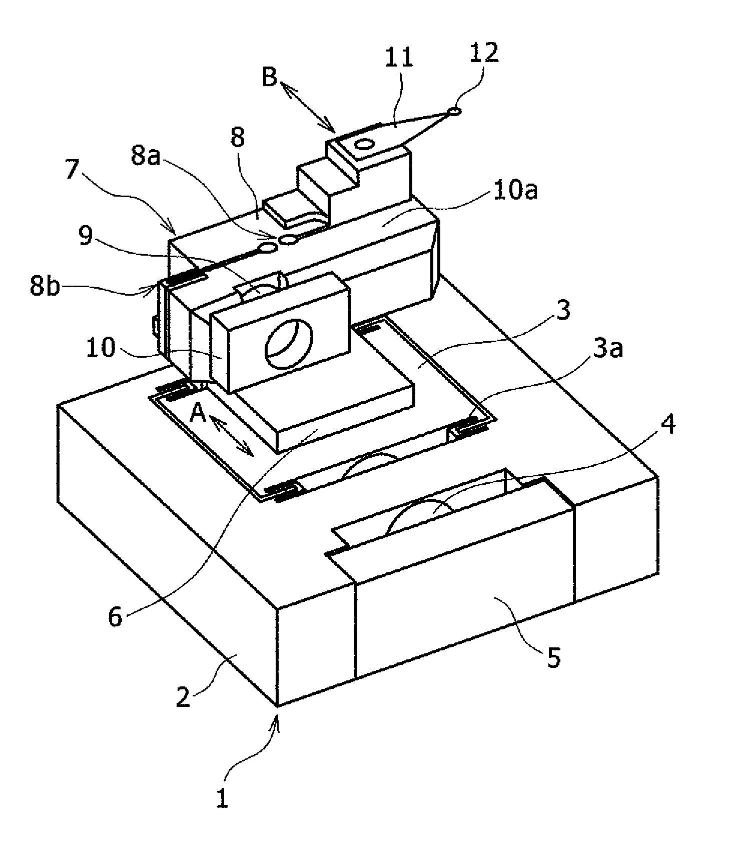
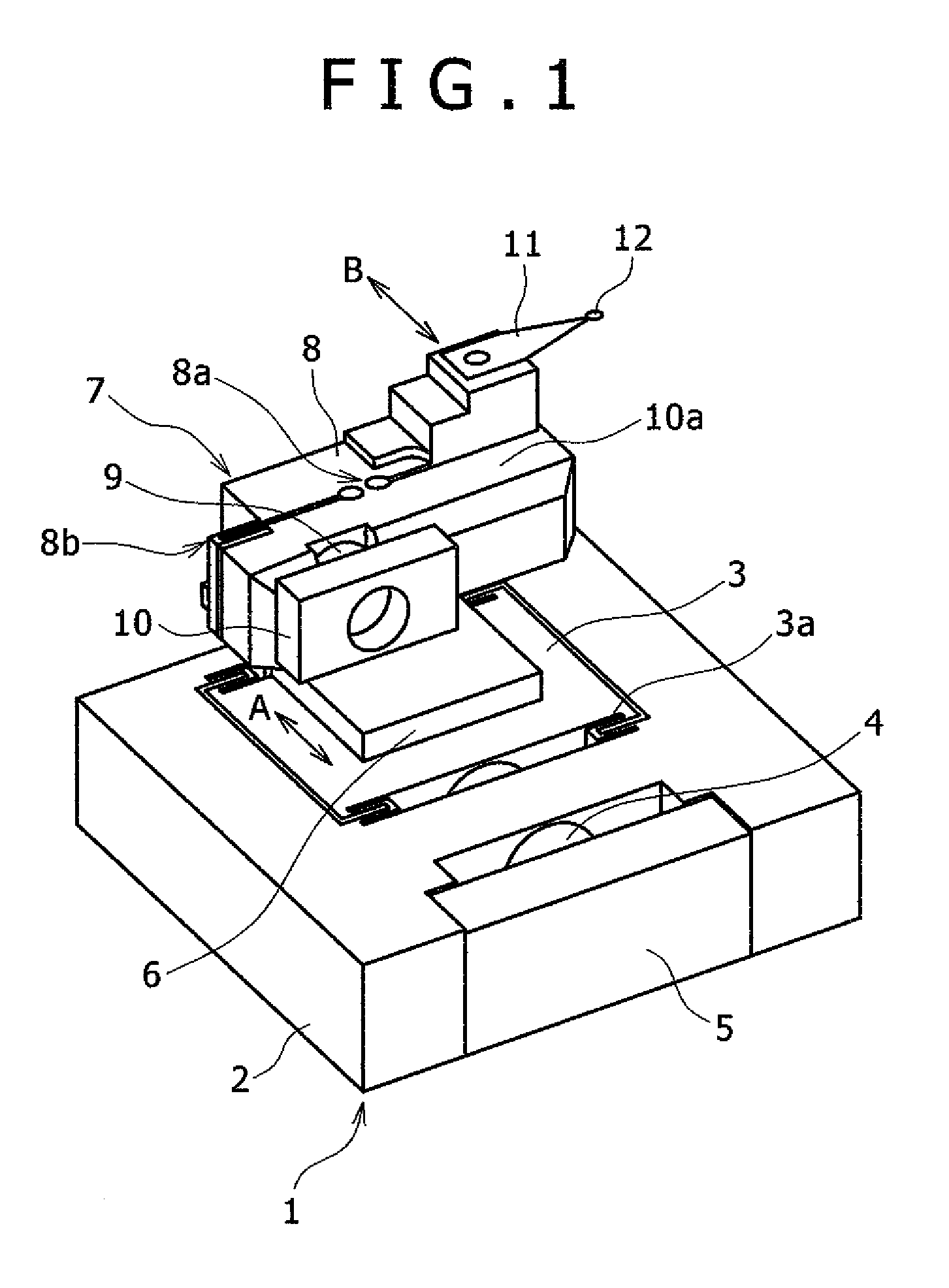
[0018]FIG. 1 is an overall view of the mechanical part of a magnetic head-positioning servo system according to a first embodiment. FIG. 2 is an overall view of the mechanical part of a magnetic disk test system using the magnetic head-positioning servo system shown in FIG. 1. FIG. 3 is a view showing the relation between a track and a magnetic disk to be tested by the magnetic disk test system shown in FIG. 2.

[0019]The magnetic disk test system is a system for testing the characteristics of a magnetic disk by a magnetic head reading the magnetic information written in advance to the magnetic disk as well as the magnetic information written to the magnetic disk by the magnetic head.

[0020]In FIG. 1, the mechanical part of the magnetic head-positioning servo system is configured such that a second fine actuator, namely a piezo-actuator 7 is mounted on a first fine actuator, namely a piezo-stage 1. The piezo-stage 1 includes a base 2, a moving table 3, support members 3a for supporting...

second embodiment

[0050]FIG. 5 is a schematic view of a magnetic head-positioning servo system according to a second embodiment. The mechanical part of the second embodiment is the same as that of the first embodiment.

[0051]The eccentricity compensation table data storage circuit 26 inputs an instruction value based on the eccentricity compensation table data that is prepared in advance to the piezo-actuator driver 27 to compensate the eccentricity.

[0052]The piezo-actuator driver 27 applies a voltage corresponding to the instruction value to the piezo-actuator7 to compensate the eccentricity by the piezo-actuator 7.

[0053]The displacement of the piezo-stage 1 from the reference position is detected by the position sensor 30, and is input to the piezo-stage compensation circuit 29. The piezo-stage compensation circuit 29 inputs an instruction value to the piezo-stage driver 31.

[0054]Based on the instruction value from the piezo-stage compensation circuit 29, the piezo-stage driver 31 generates a drive ...

third embodiment

[0058]FIG. 6 is a schematic view of a magnetic head-positioning servo system according to a third embodiment. The configuration of the mechanical part of the third embodiment is the same as those of the first and second embodiments.

[0059]The eccentricity compensation table data storage circuit 26 inputs an instruction value, based on the eccentricity compensation table data that is prepared in advance, to a current pulse-controlled piezo-actuator driver 32 to compensate the eccentricity.

[0060]The current pulse-controlled piezo-actuator driver 32 applies a current pulse corresponding to the instruction value to the piezo-actuator 7 to compensate the eccentricity by the piezo-actuator 7.

[0061]The displacement of the piezo-stage 1 from the reference position is detected by the position sensor 30, and is input to the piezo-stage compensation circuit 29.

[0062]The piezo-stage compensation circuit 29 inputs an instruction value to the piezo-stage driver 31.

[0063]Based on the instruction va...


PUM

PropertyMeasurementUnit
displacementaaaaaaaaaa
natural frequencyaaaaaaaaaa

Abstract

A magnetic head-positioning servo system is provided to accurately test a magnetic disk with a track written in advance, by providing two fine actuators. The second fine actuator, to which a magnetic head is attached, is mounted on the first fine actuator. The second fine actuator has a larger generating displacement than a generating displacement of the first fine actuator, and lets the magnetic disk to follow the eccentricity of the track. In this way, the positioning accuracy can be increased.

Description

FIELD OF THE INVENTION[0001]The present invention relates to a magnetic head-positioning servo system, a magnetic head test system and a magnetic disk test system. More particularly, the present invention relates, for example, to a test system for positioning a magnetic head to a target track on a magnetic disk, which is particularly suitable when the eccentricity of the track is large.BACKGROUND OF THE INVENTION[0002]Magnetic disks, as well as magnetic heads used for writing and reading data to and from magnetic disks are tested in relation to their characteristics by a test system before being mounted to magnetic disk systems (see, for example, JP-A No. 268955 / 2006). Magnetic head test is performed in the form of head gimbal assembly (HGA) in which a head-suspension and a magnetic head are assembled together. At the time of testing, a magnetic head is located above a magnetic disk rotated by a rotating spindle to write and read data to and from the magnetic disk.[0003]A piezoelect...

Claims


Application Information

Patent Timeline
Patent Type & Authority Patents(United States)
IPC IPC(8): G11B5/596
CPCG11B5/455G11B5/4555G11B5/5552G11B5/59627G11B19/048
Inventor NAKAMURA, SHIGEOSUDO, KIMIHIKOSUGIYAMA, TOSHINORIMATSUDA, YASUHIROYAMAMOTO, YUKIOSAKURAI, YOSHIHIRO
Owner HITACHI HIGH-TECH CORP
Why Eureka
Try Eureka