
Apparatus and method for non-destructive testing

a non-destructive testing and apparatus technology, applied in the direction of material analysis using wave/particle radiation, instruments, nuclear engineering, etc., can solve the problems of defective bonding, inability to prove that any given assembly is sufficiently strong to have a high probability of not failing in service, and weak bond areas that cannot be observed with conventional ultrasound or thermal techniques

Active Publication Date: 2012-04-17
LSP TECH INC
View PDF46 Cites 14 Cited by
  • Summary
  • Abstract
  • Description
  • Claims
  • Application Information

AI Technical Summary

Benefits of technology

"The present invention provides a way to inspect bonded structures in real-time and detect stress waves caused by bond failure. It also allows for remote delivery of a laser beam to a surface. The invention can be used with various materials and can determine the strength of unbonded solid materials. Additionally, it can be used in other applications that require remote delivery of a localized stress wave and diagnosis of the resultant stress waves."

Problems solved by technology

The typical means of testing bonded structures is a destructive proof test that may validate an assembly process, but does not prove that any given assembly is sufficiently strong to have a high probability of not failing in service.
These weak bond areas are not observable with conventional ultrasound or thermal techniques because the bond between layers, while weak, is intact or in contact and no delamination area exists that would be visible to standard inspection techniques.
These defective bonds could arise from (1) improper preparation of the surfaces to be bonded; (2) improper mixing, application, and / or curing of the adhesive; or (3) contamination of the surfaces before bonding.
Unfortunately, the electron beam generator is massive, therefore not portable, and the output beam cannot be conveniently moved around the surface of an aircraft to test the skin or other structural members.

Method used


Image

  • Apparatus and method for non-destructive testing
  • Apparatus and method for non-destructive testing
  • Apparatus and method for non-destructive testing

Examples


Embodiment Construction

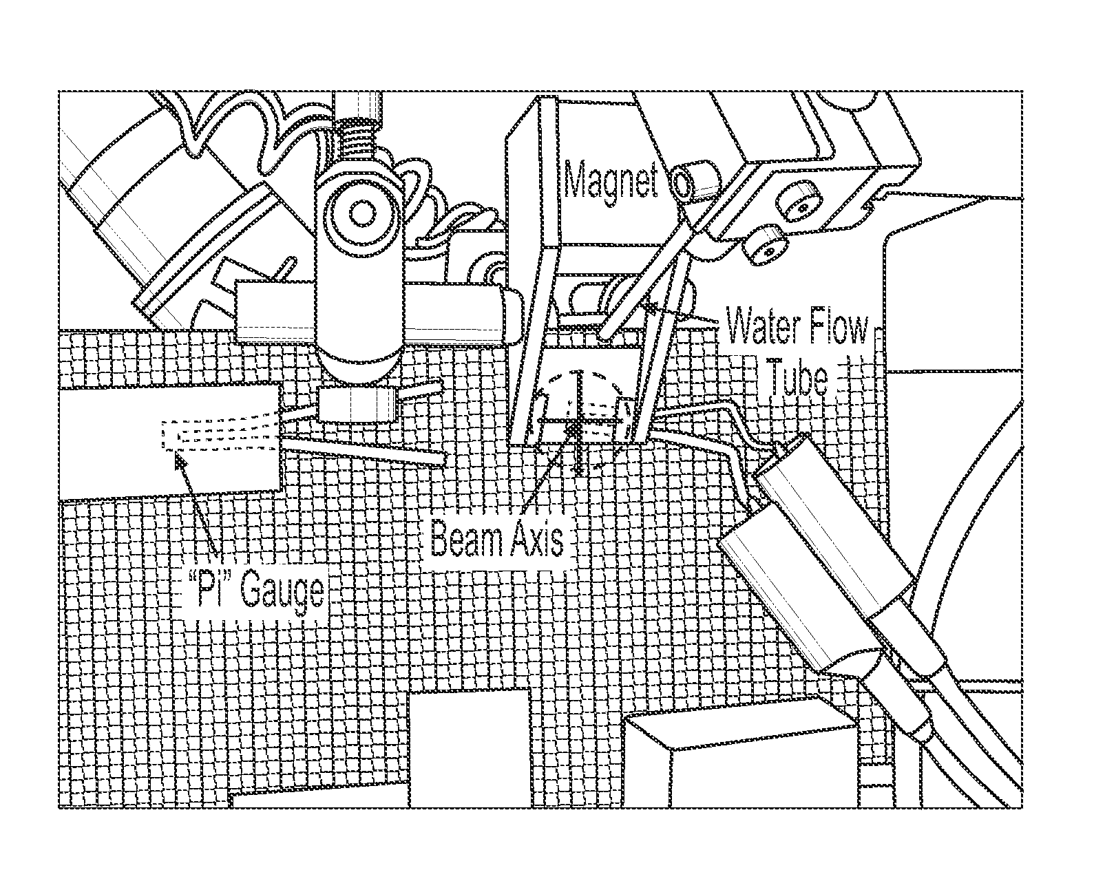
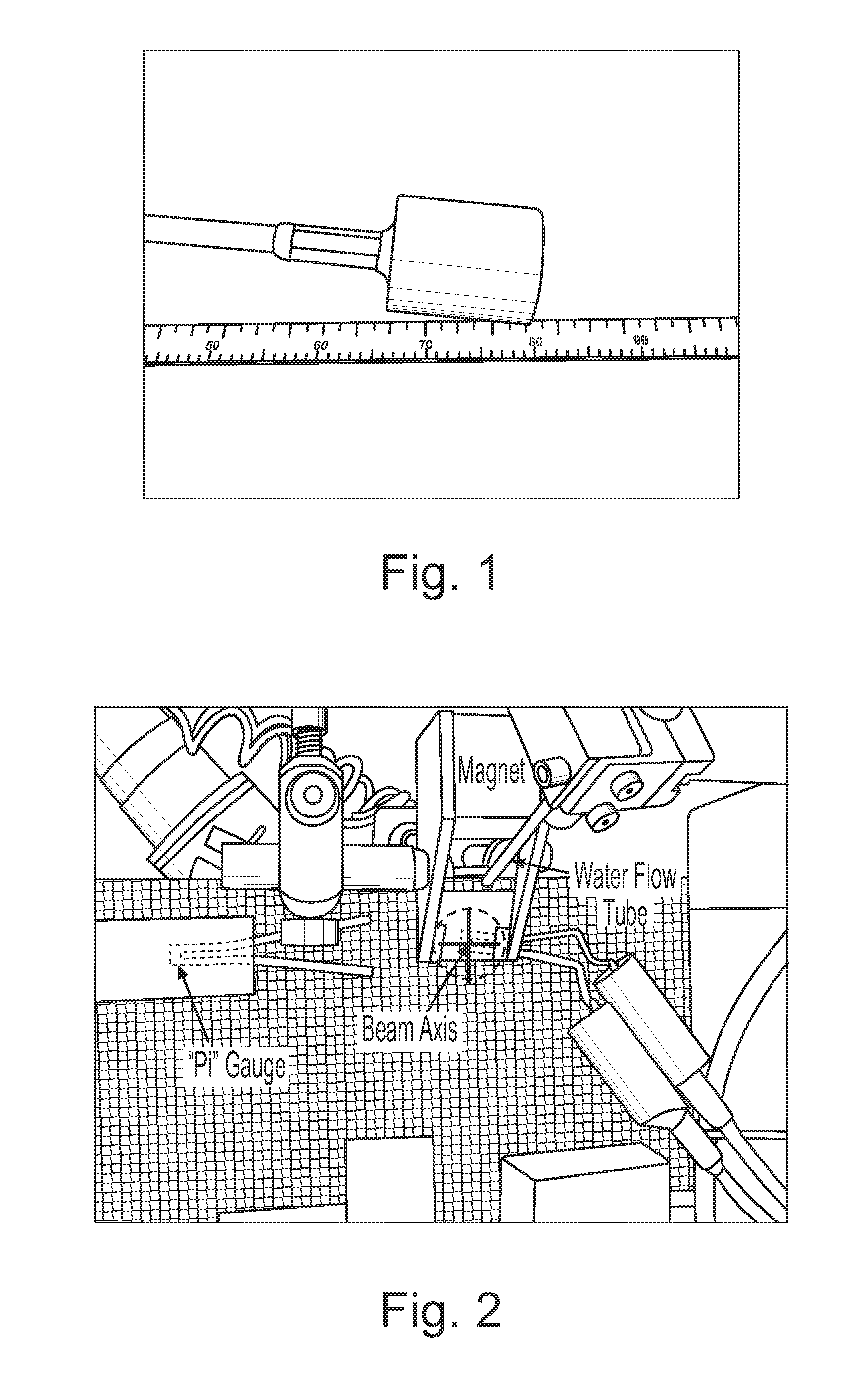
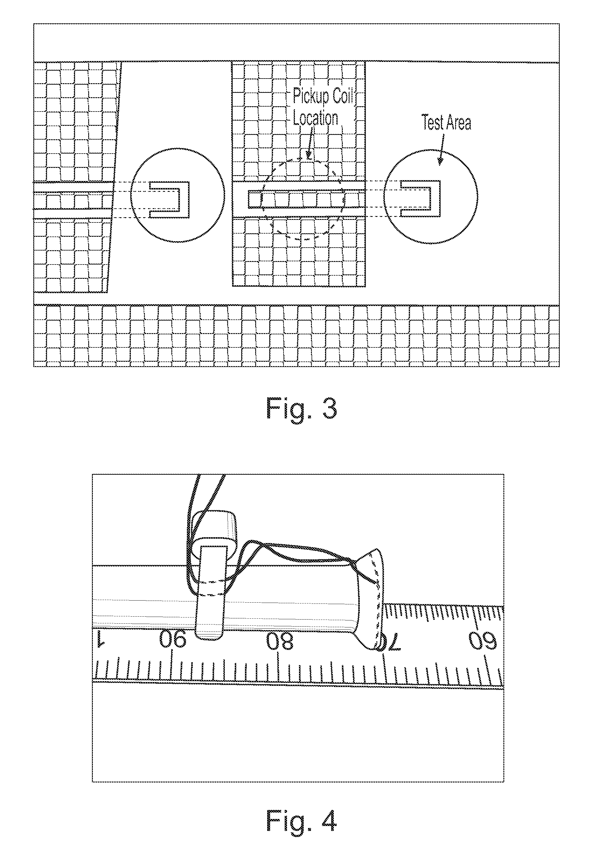
[0032]The use of short laser pulses has been demonstrated to be an effective means of generating stress waves for proof testing of adhesive bonds in composite structures. The process of laser bond inspection (LBI) entails deposition of laser energy at the front surface of a structure (which generates a compressive stress wave), propagation of the stress wave to the back surface or first free surface, reflection of the compressive stress wave to form a tensile wave, and breaking of weak bonds in the structure with the tensile wave as it travels back toward the front surface. For practical implementation of this process in a production environment, a tool must be moved along the structure to be tested and a test result for the bond must be reported at each inspection point.

[0033]Process head concepts have been developed and demonstrated for delivery of the laser beam pulses to the surface to be tested. Sensors have also been developed for indicating whether or not the bond failed unde...


PUM


Abstract

A diagnostic means to enable real-time inspection of bonded structures. The disclosed apparatus detects bond failure stress waves on-axis from the front side (beam application side). Pi-box and pi-rail EMAT gauges can be used with the disclosed apparatus. An inductively coupled EMAT may also be employed. An improved means to remotely deliver an interrogating laser beam to a surface is provided. The process head may utilize a water column or a water film. The water film process head may include the use of either a single water film or two spaced apart water films. The disclosed apparatus can be used with bonded composite structures, bonded structures using various materials, and to determine the dynamic strength of unbonded solid materials. The apparatus may also be used in other applications that require remote flexible delivery of a localized stress wave to a material and / or diagnosis of the resultant stress waves.

Description

[0001]This application claims the benefit of prior filed U.S. Provisional Application No. 60 / 610,102 filed Sep. 15, 2004, in the name of the above named inventors, the disclosure of which is incorporated herein by reference thereto.BACKGROUND OF THE INVENTION[0002]1. Field of the Invention[0003]The present invention relates to non-destructive inspection of composite structures.[0004]2. Description of the Related Art[0005]A critical need in the aircraft industry is the non-destructive inspection (NDI) of composite structures assembled with adhesive bonds. The typical means of testing bonded structures is a destructive proof test that may validate an assembly process, but does not prove that any given assembly is sufficiently strong to have a high probability of not failing in service.[0006]In particular, it is of interest to find weakly bonded layers in multi-layer carbon-fiber / resin-matrix skins and internal members. These weak bond areas are not observable with conventional ultraso...

Claims


Application Information

Patent Timeline
Patent Type & Authority Patents(United States)
IPC IPC(8): G01M7/00
CPCG01N29/043G01N29/2412G01N29/4454G01N2291/0231G01N2291/267G01N2291/2694
Inventor TOLLER, STEVEN M.WALTERS, CRAIG T.
Owner LSP TECH INC
Learn More