
Latching micro-magnetic relay and method of operating same

a micro-magnetic relay and latching technology, applied in the field of electrostatic switching relays, can solve the problems of large relay size that no longer meets the requirements, requires large current for switching, drawbacks and limitations

Active Publication Date: 2012-04-17
RUAN MEICHUN +1
View PDF22 Cites 7 Cited by
  • Summary
  • Abstract
  • Description
  • Claims
  • Application Information

AI Technical Summary

Benefits of technology

The solution enables efficient switching between stable states with high contact force, low magnetic interference, and high reliability, facilitating dense relay deployment while reducing manufacturing complexity and costs.

Problems solved by technology

Large size relay no longer meets the requirements.
Each of the prior arts, though providing a unique approach to make latching electromechanical relays and possessing some advantages, has some drawbacks and limitations.
Some of them may require large current for switching.
In general, permanent magnet with high temperature stability is brittle and easy to break.
It could become a reliability concern if it is used as a moving part which experiences millions of cycles of impact during the service.
These drawbacks and limitations can make manufacturing difficult and costly, and hinder their value in practical applications.
Or it needs to be positioned far away from the magnet to get the relative uniform field, which is often weak and results in undesirable performance of the device.
But a substantial size magnet is always needed, which causes long range magnetic field interference on the neighboring relays, magnetic devices or tools.
Shrinking the device size, especially the magnet, is difficult.
The reason is that aligning the cantilever with the magnetic field line, which curves dramatically and often points in different directions near small magnets, becomes impractical.

Method used


Image

  • Latching micro-magnetic relay and method of operating same
  • Latching micro-magnetic relay and method of operating same
  • Latching micro-magnetic relay and method of operating same

Examples


Embodiment Construction

[0034]It should be appreciated that the particular implementations shown and described herein are examples of the invention and are not intended to otherwise limit the scope of the present invention in any way. Indeed, for the sake of brevity, conventional electronics, manufacturing, MEMS technologies and other functional aspects of the systems (and components of the individual operating components of the systems) may not be described in detail herein. Furthermore, for purposes of brevity, the invention is frequently described herein as pertaining to a micro-electronically-machined relay for use in electrical or electronic systems. It should be appreciated that many other manufacturing techniques could be used to create the relays described herein, and that the techniques described herein could be used in mechanical relays, optical relays or any other switching device. Further, the techniques would be suitable for application in electrical systems, optical systems, consumer electron...


PUM


Abstract

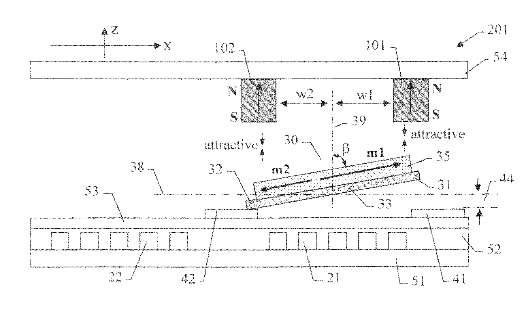
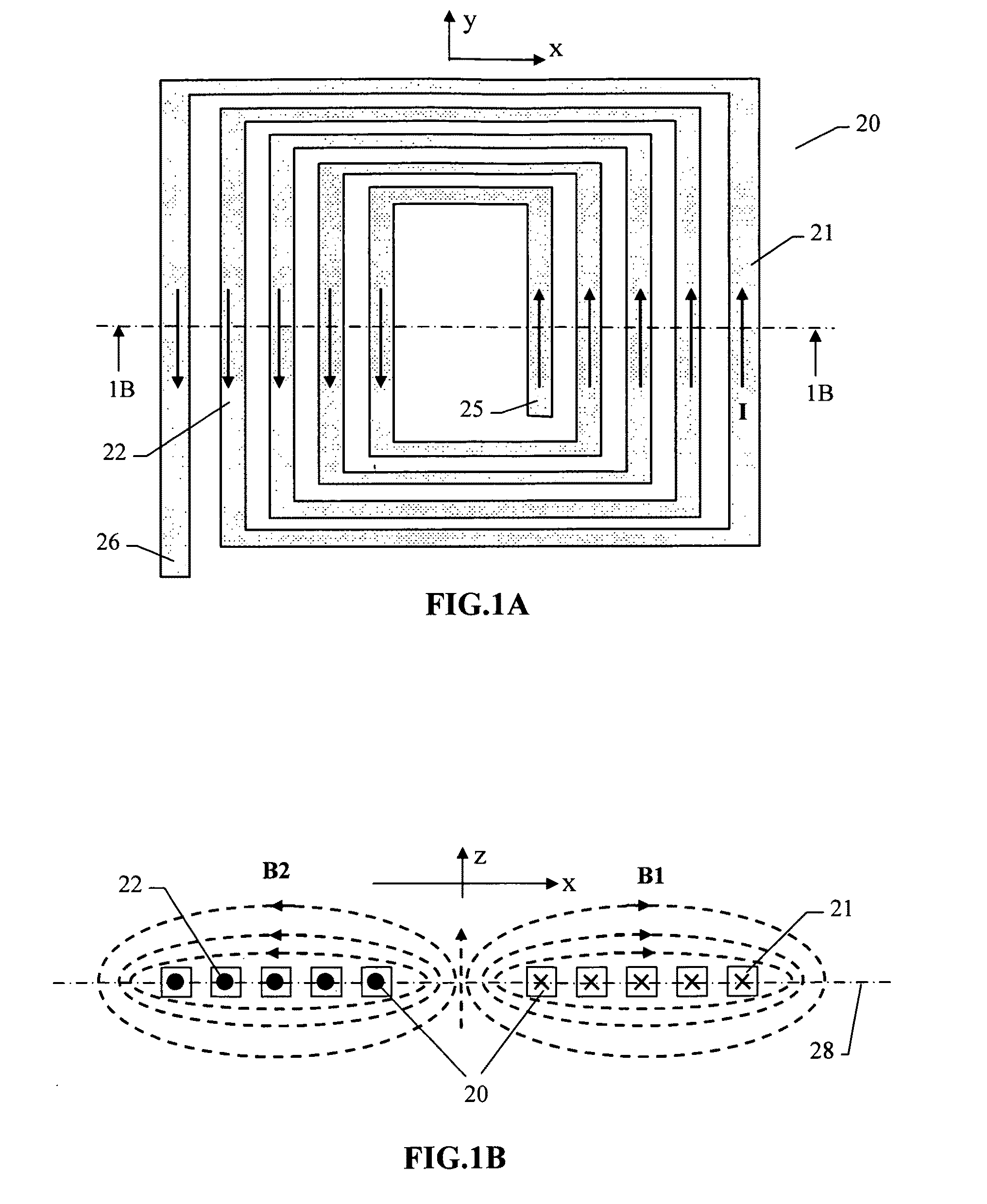
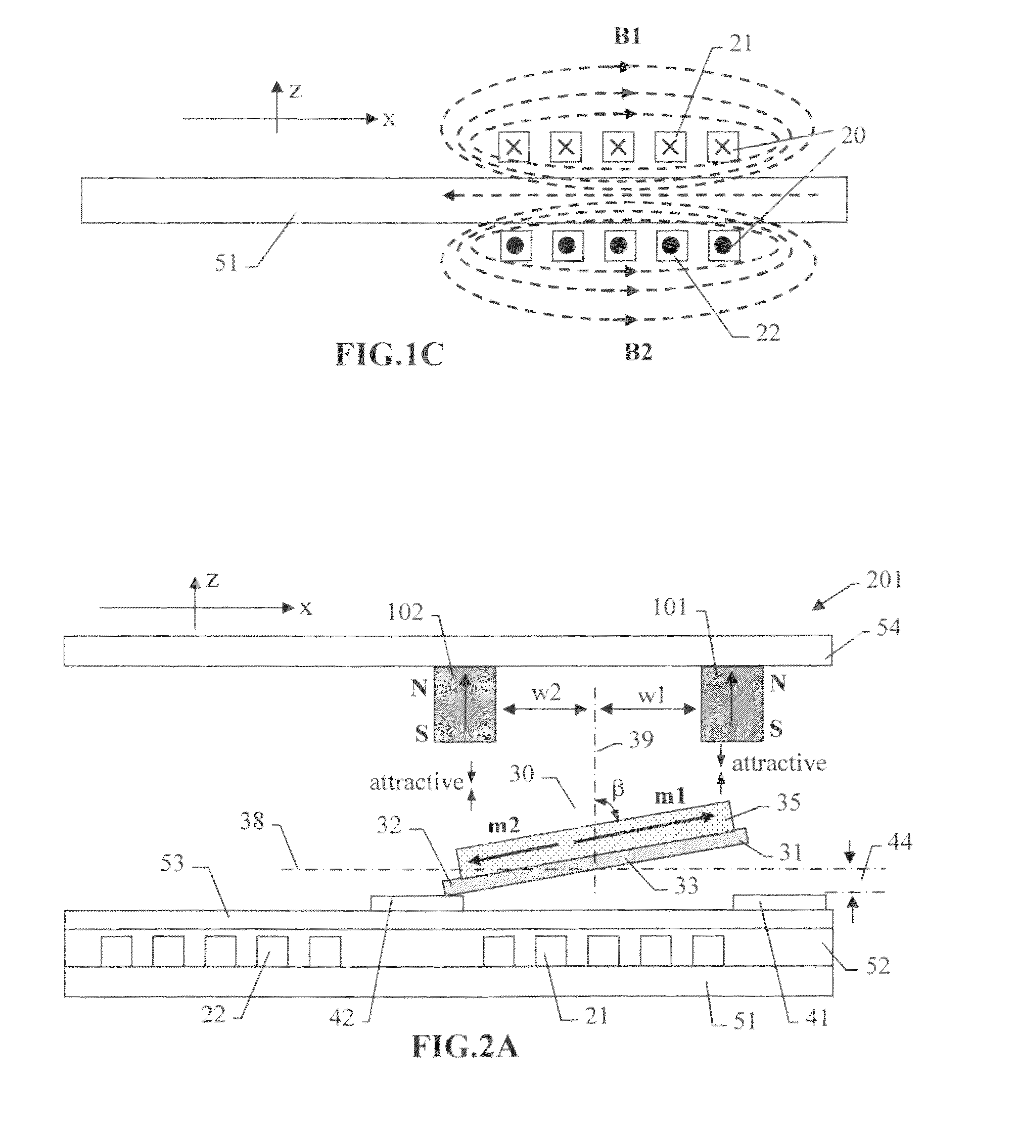
A micro-machined magnetic latching relay has a moveable cantilever comprising a soft magnetic material and having a first end and a second end. The cantilever has a rotational axis which is a flexure supported by a substrate. A first permanent and a second permanent magnet are disposed near the first end and the second end of the cantilever respectively. Each of the two magnets produces a magnetic force and a torque on the cantilever. The first permanent magnet, second permanent magnet and the substrate are arranged to provide two stable positions for the cantilever. An electromagnet provides a temporary switching magnetic field to adjust the local magnetizations across the magnetic cantilever, causing changes of magnetic forces and torques on the cantilever. As a result, the direction of a sum of torque on the cantilever is reversed. Therefore, the cantilever is switched from one stable position to the other.

Description

CROSS-REFERENCE TO RELATED APPLICATIONS[0001]Not ApplicableFEDERALLY SPONSORED RESEARCH[0002]Not ApplicableFIELD OF THE INVENTION[0003]The present invention relates to electronically switching relays. More specifically, the present invention relates to latching micro-magnetic relays and to methods of formulating and operating micro-magnetic relays.BACKGROUND OF THE INVENTION[0004]Relays are typically electrically controlled devices that open and close electrical contacts to affect the current flow in an electrical circuit or the laser path in the fiber optical system. Relays are widely used in telecommunications, radio frequency (RF) communications, portable electronics, consumer and industrial electronics, aerospace, optical fiber communications, and other systems.[0005]A common electro-mechanical relay comprises an electromagnetic mechanism, an armature, and a contact mechanism having a fixed contact and a movable contact which are selectively closed and opened by a pivot motion o...

Claims


Application Information

Patent Timeline
Patent Type & Authority Patents(United States)
IPC IPC(8): H01H51/22
CPCH01H50/005H01H2050/007
Inventor RUAN, MEICHUNWEI, QUNYING
Owner RUAN MEICHUN
Learn More