Foundation for monopole wind turbine tower

a technology of wind turbine towers and foundations, applied in the direction of towers, buildings, constructions, etc., can solve the problems of increased construction costs, unefficient shape, and high installation cost of wind turbines, so as to reduce construction labor, reduce material costs and construction labor, and enhance the use of plain structural concrete

Active Publication Date: 2012-04-24
ANEMERGONICS
View PDF62 Cites 45 Cited by
  • Summary
  • Abstract
  • Description
  • Claims
  • Application Information

AI Technical Summary

Benefits of technology

[0008]The disclosed invention provides an improved foundation for use with wind turbine monopole towers. The innovation accomplishes a significant reduction of material costs and construction labor. The foundation is located below grade, with only a small stub pier exposed, accomplished using a specific concrete forming method and longer anchor bolts. It enhances the use of plain structural concrete by using fiber additives to reduce concrete cracking. It is characterized by a preferred circular (or multi-sided polygonal) cross sectional shape and a stanchion to capture helically arranged reinforcement and precisely locate anchor bolts.

Problems solved by technology

The largest percentage of installed cost for wind turbines—certainly for small wind turbines—is attributable to towers and foundations.
They are favored for their visual appeal and maintenance simplicity, but are more costly than guyed towers.
Traditional turbine foundations use a square cross section of the foundation, which is not an efficient shape.
While the entire block contributes mass that is useful in resisting the applied overturning moment, the moment arm to the corners can not be assumed because there is no a priori assurance of the loading direction.
The corners of the block are essentially wasted space and materials.
Another aspect of prior art towers that adds to the cost of installation is having the entire top of the foundation above-ground.
This requires extensive forms to create the desired shape and structure, necessitating more materials, design, and labor to install.
This method is very time consuming and costly.
The possibility of error during the fabrication is also significant.
For people not familiar with the materials, or without the tools to properly manipulate them, this can be a very time-consuming process, with great room for error.

Method used


Image

  • Foundation for monopole wind turbine tower
  • Foundation for monopole wind turbine tower
  • Foundation for monopole wind turbine tower

Examples


Embodiment Construction

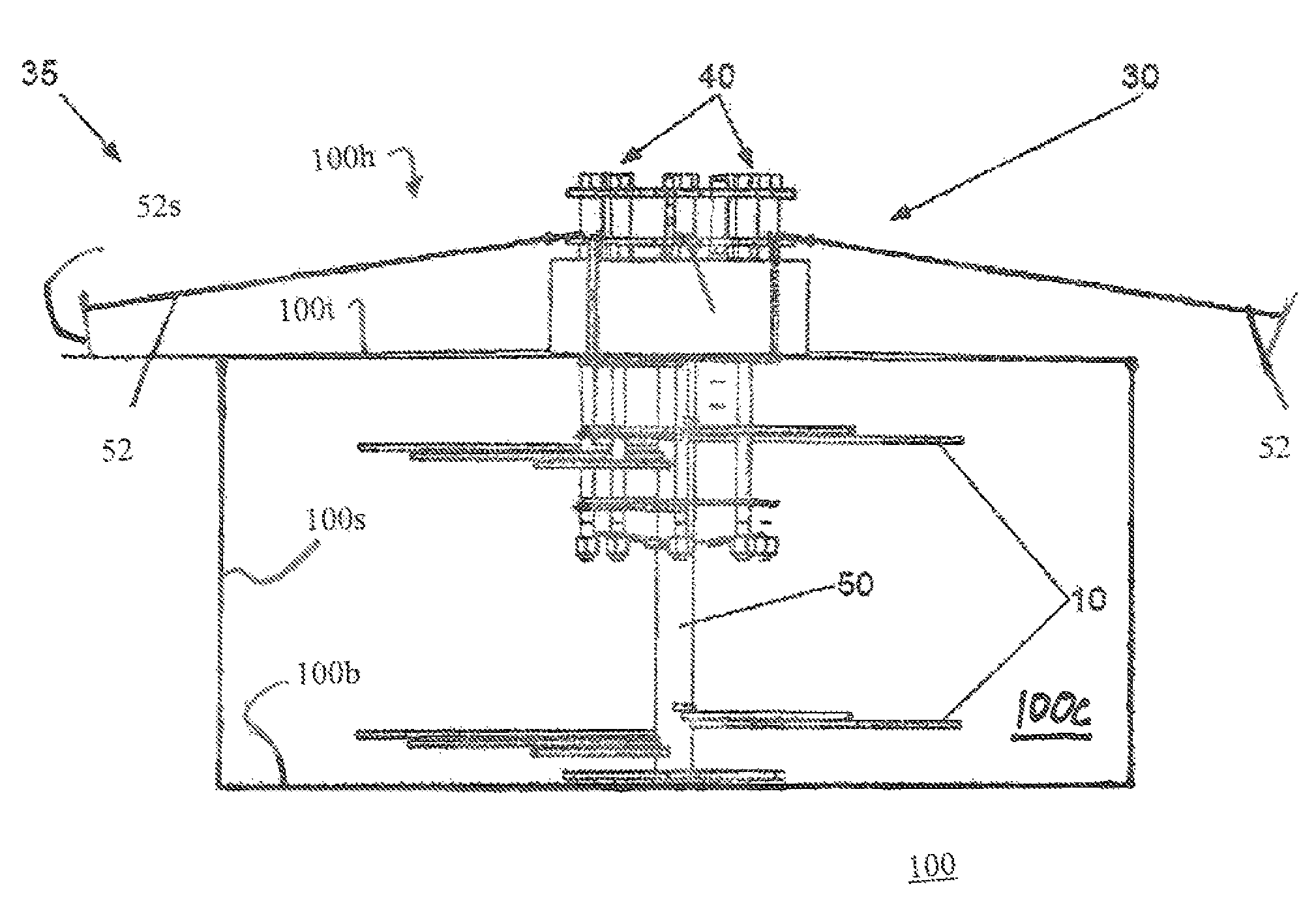
[0020]The inventions disclosed herein entail improvements to wind turbine foundation design.

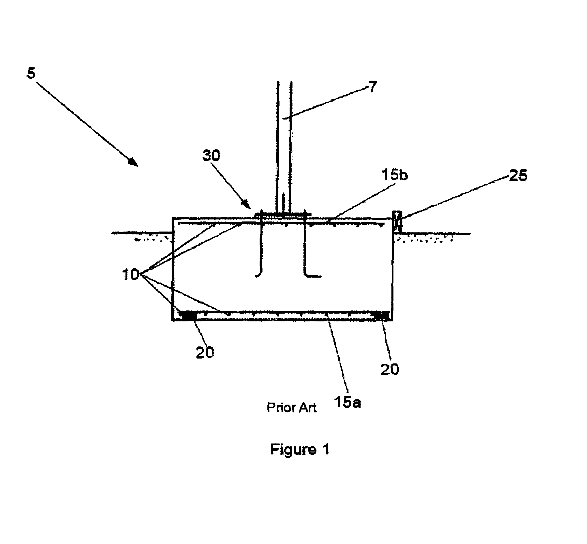
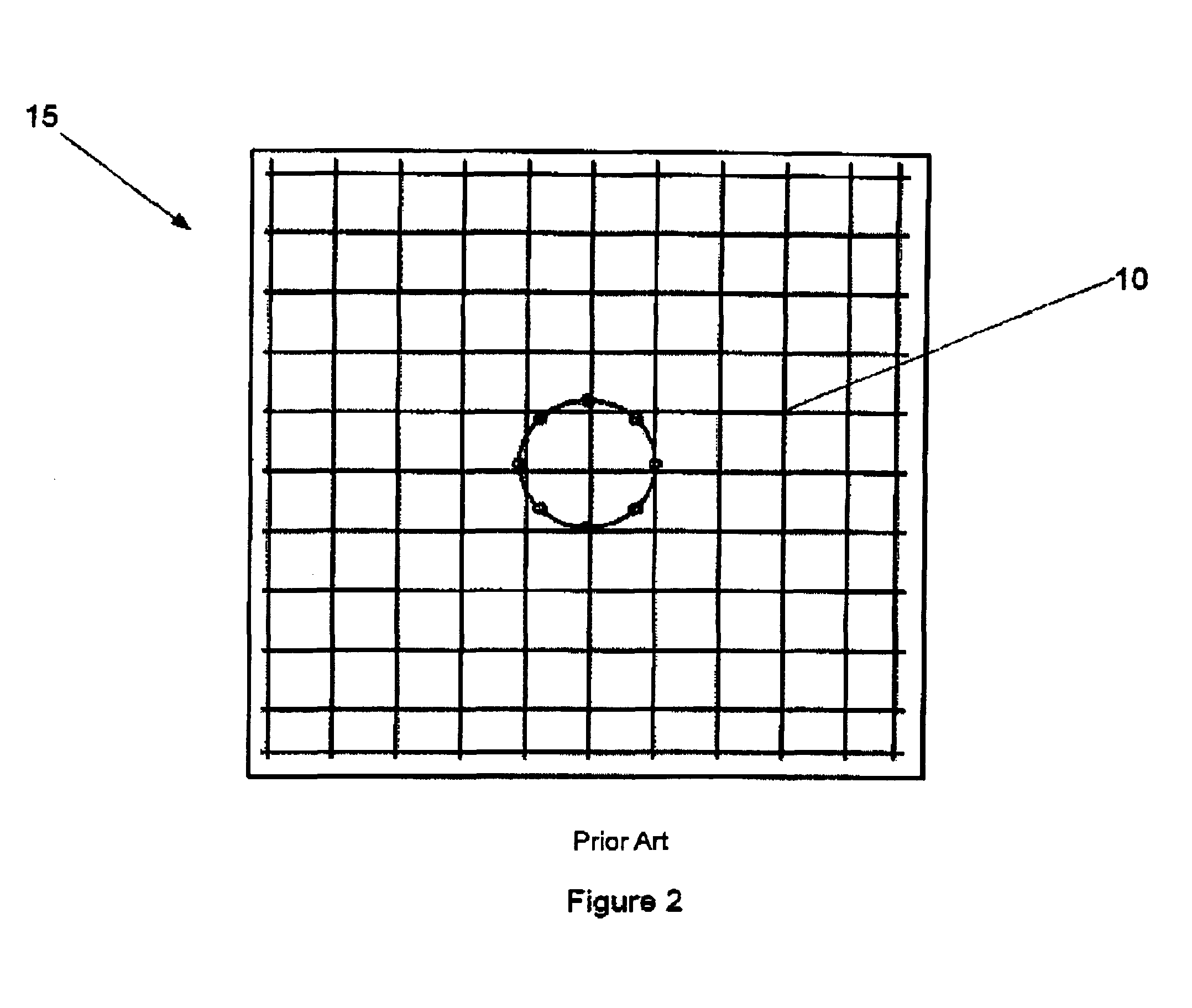
[0021]A prior art mat foundation 5, is shown in FIG. 1. The cross-section, as shown in FIG. 2, is that of a square. A tower 7 is attached to the foundation 5. The foundation width and depth are determined by engineering analyses, taking into consideration the applied loads (overturning moment, side shear and axial force), soil conditions, frost depth, anchor bolt configuration and other factors. Steel reinforcing bars 10 are placed orthogonally a certain distance apart so as to create a reinforcing grid 15a and 15b in both horizontal directions. Detail of the reinforcing bars 10 and the reinforcing grid 15a and 15b are shown in FIG. 2. The bars 10 are fastened together at their intersections using wire ties, as is typical of structurally reinforced concrete. One of the most tedious tasks in constructing the mat foundation 5 is tying the reinforcing bars 10 at their intersections. In a typical...


PUM


Abstract

An innovation is disclosed which relates to a wind turbine foundation. A circular foundation using fiber reinforced concrete has optional circular reinforcement rods. The foundation includes a vertical stanchion that rests in the bottom of an excavated hole and supports anchor bolts and reinforcement bars in a predetermined configuration while concrete is poured into the hole. All the necessary foundation materials can be combined in a simple and compact kit which can be shipped to a customer.

Description

RELATED APPLICATIONS[0001]This application claims priority under 35 U.S.C. 119(e) to U.S. Provisional Patent Application No. 60 / 900,287 which was filed on Feb. 8, 2007 and which is incorporated herein by reference.FIELD OF THE INVENTION[0002]The invention relates to a wind turbine foundation. Specifically the invention relates to the design of a foundation kit for monopole towers used with small and residential-scale wind turbines.BACKGROUND OF THE INVENTION[0003]Wind turbines are renewable energy devices that are being deployed in greater numbers as awareness grows of fossil fuels' disadvantages. The largest percentage of installed cost for wind turbines—certainly for small wind turbines—is attributable to towers and foundations. Development of innovative towers and foundations that have the potential for simplifying turbine installation and reducing cost, will promote more widespread deployment. Of particular interest are free-standing (no guy wires or ancillary supports) monopole...

Claims


Application Information

Patent Timeline
Patent Type & Authority Patents(United States)
IPC IPC(8): E02D27/50E02D27/42E04H12/00
CPCE02D27/42F03D13/22Y02E10/728Y02E10/72
Inventor MIGLIORE, PAUL GERALD
Owner ANEMERGONICS
Why Eureka
Try Eureka