Flash-bang grenade with greater flash intensity

Inactive Publication Date: 2012-04-24
UNITED STATES OF AMERICA THE AS REPRESENTED BY THE SEC OF THE ARMY
View PDF11 Cites 29 Cited by
  • Summary
  • Abstract
  • Description
  • Claims
  • Application Information

AI Technical Summary

Benefits of technology

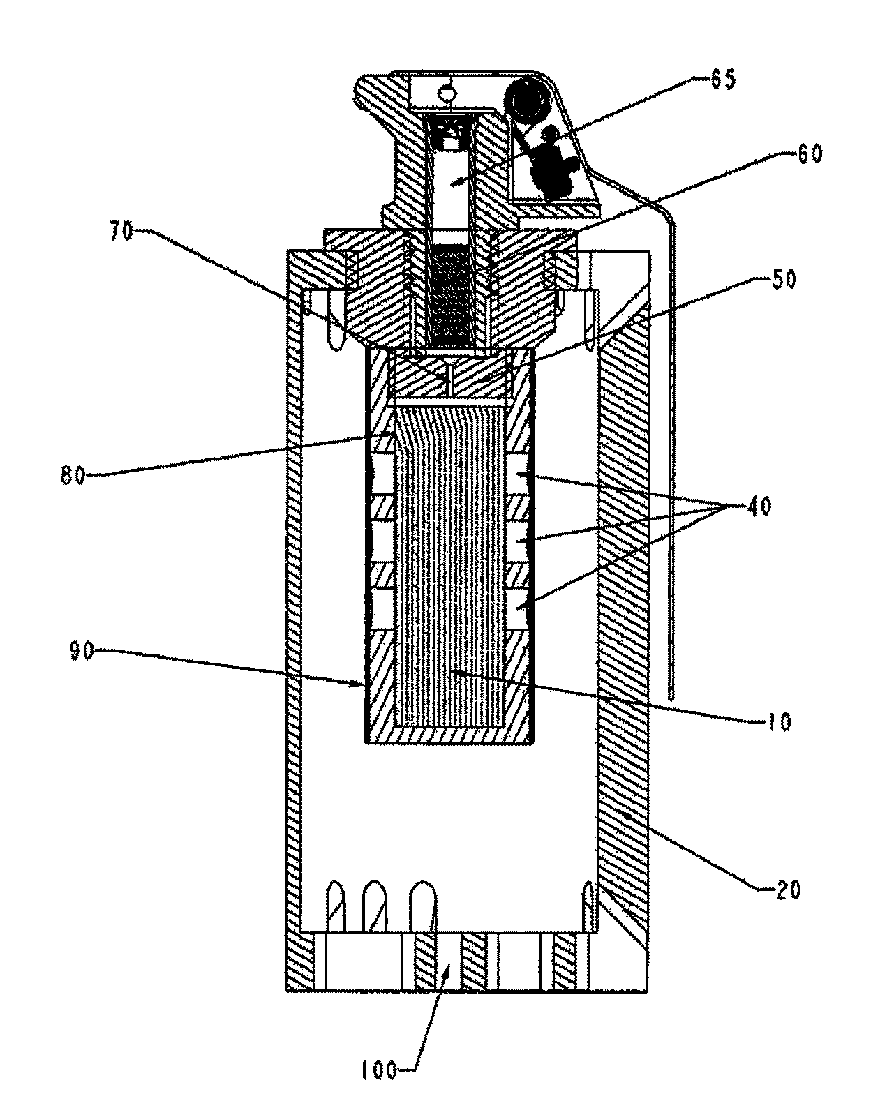
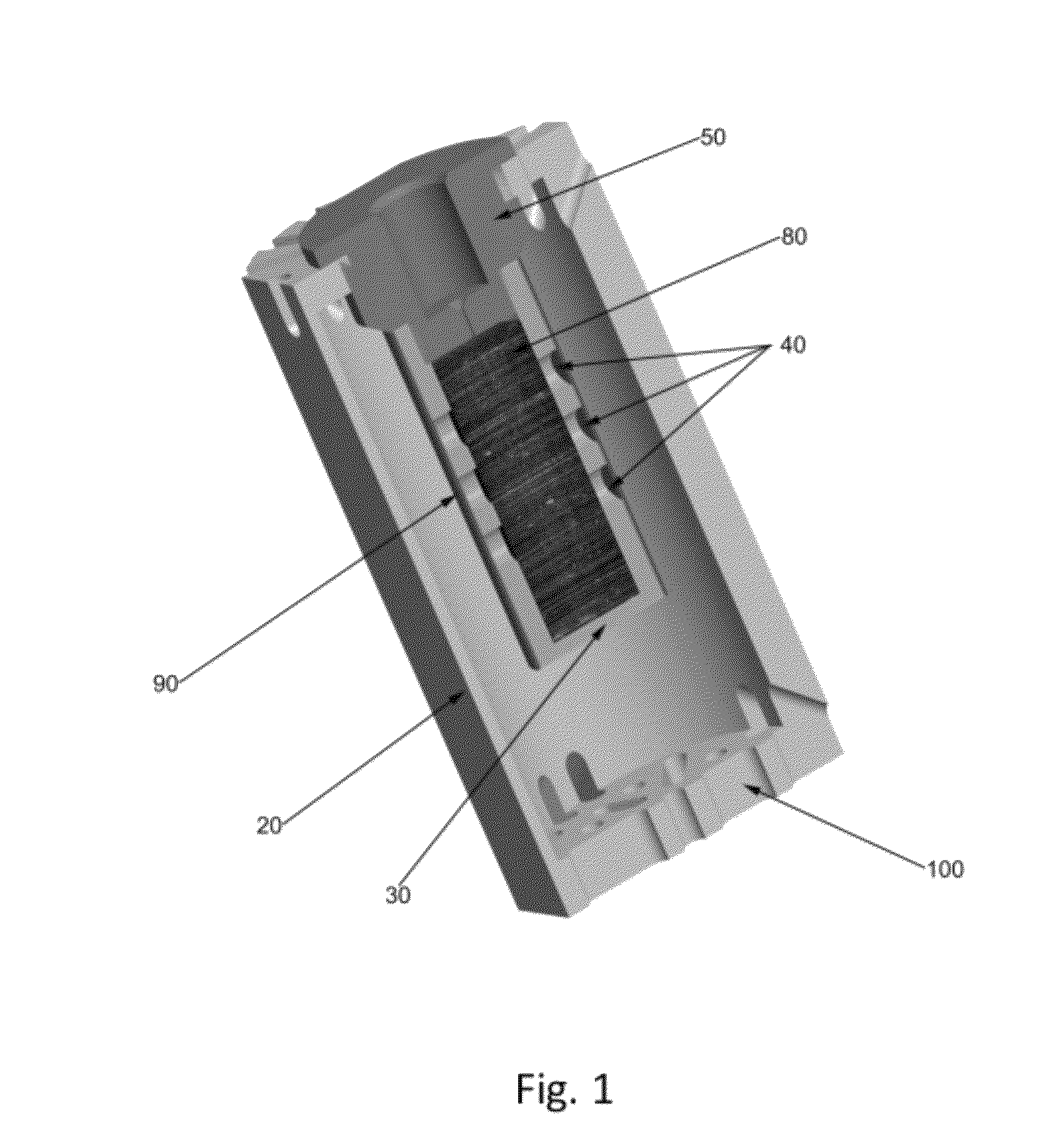
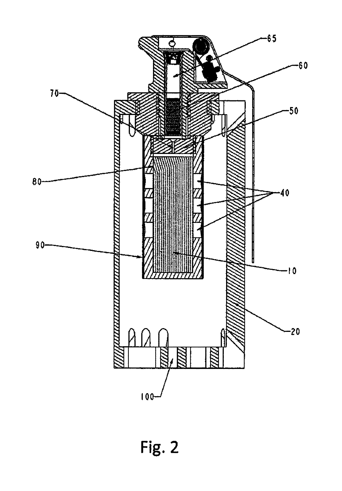
[0008]The present invention incorporates a very specific pyrotechnic formulation in combination with a very particular reaction chamber design, to momentarily contain or hold back the escape of the reaction, thereby providing a more controlled subsonic deflagrate flash-bang than possible in the prior art, i.e. achieving a higher level of energetic reaction and brighter/more intense flash. The reaction chamber, housed within the body of the flash-bang grenade, has a unique design which incorporates a rigid, non-fragmenting charge holder having a series of vent holes thereabout, and a consumable inner sleeve (i.e. within the charge holder) and a consumable outer sleeve (exterior to the charge holder)—both s

Problems solved by technology

Unfortunately, while the sound level of the M84 and corresponding civilian equivalents (such as the CTS Model 7290 Flash Bang

Method used


Image

  • Flash-bang grenade with greater flash intensity
  • Flash-bang grenade with greater flash intensity
  • Flash-bang grenade with greater flash intensity

Examples


example i

Determination of Sound & Flash Intensity

[0025]A series of repetitive performance tests were conducted with the subject invention, the results of which are detailed in Table I, immediately below. The preferred embodiment of the present invention used in the series of tests included a charge of 9 grams of a pyrotechnic mix of about 53.7 wt. % strontium nitrate oxidizer; about 40 wt. % aluminum powder metallic fuel; about 5 wt. % sulfur non-metallic fuel; about 1 wt. % boric acid pH stabilizer; and finally, about 0.3 wt. % M5 Cab-o-sil free flow / anti-caking agent and a reaction chamber of the subject design. The particular preferred reaction chamber used in the tests had a 0.005 inch aluminum inner sleeve, 80, an aluminum charge holder, 30, with 6 sets of equally spaced, about the circumference, groups of 3 longitudinally aligned venting holes, 40, and an outer or external sleeve, 90, of Thomas and Betts HS tubing, particularly HS4-30LR Shrink-Kon® Tubing, which is a heavy-wall heat-sh...

example ii

Determination of Safety Re: Incendiary Effect

[0027]A series of incendiary tests were conducted using the current M84 stun grenade and a flash-bang grenade of the present invention, as detailed in Example I, above. The tests comprised detonating a series of such stun / flash-bang grenades directly on paper, cotton, and standard Army Combat Uniform material. While in the case of both the current M84 and flash-hang grenades, none of the various materials were ignited—with the M84 the cotton smoldered, repeatably—an effect which was not observed with the flash-bang grenades of the present invention. Therefore the subject inventive flash-bang grenade proved safer in use (not only to materials regarding which the grenade may contact upon use—but, also to the user, in the event of an accident or to anyone in the immediate vicinity upon detonation) vs. the current, prior art, M84 stun / flash-bang grenade.


PUM


Abstract

A safer flash-bang grenade that yields the state of the art sound intensity, plus a brighter, more intense flash of the order of 13.5 million candela—which effect is due to a combination of a particularly efficacious pyrotechnic formulation and a particular reaction chamber design that momentarily retains or holds-back the reaction escape until the desired intensity is reached. The particular pyrotechnic formulation is based upon a strontium nitrate oxidizer in conjunction with an aluminum powder metallic fuel and a sulfur non-metallic fuel. The particular reaction chamber design includes a relatively rigid, non-fragmenting charge holder, with a slip-fit thin aluminum sleeve internal thereof and a shrink fit or other sealed sleeve external thereof.

Description

CROSS-REFERENCE TO RELATED APPLICATIONS[0001]This application claims benefit under 35 USC §119(e) of U.S. provisional patent application No. 61 / 226,033 filed Jul. 16, 2009.U.S. GOVERNMENT INTEREST[0002]The inventions described herein may be manufactured, used and licensed by or for the U.S. Government for U.S. Government purposes.FIELD OF THE DISCLOSURE[0003]This disclosure relates generally to stun grenades, and in particular to such a grenade with a significantly enhanced flash effect.BACKGROUND OF THE DISCLOSURE[0004]Stun grenades have been employed by SWAT teams and by the military for producing a non-lethal explosion to temporarily disorient and / or disable suspects, terrorists, etc. A conventional example of such a stun grenade is given in U.S. Pat. No. 4,947,753, to Nixon et al., issued Aug. 14, 1990, which disclosure is incorporated herein by reference. As disclosed in this patent, such conventional stun grenades standardly include a pull ring assembly and spring-biased strik...

Claims


Application Information

Patent Timeline
IPC IPC(8): F42B12/36F42B8/12F42B4/04F42B27/00
CPCF41A33/04F42B4/04F42B12/36F42B12/42F42B27/00
Inventor HARASTS, NICOLE D.CHOW, WILLIAM CHUNG-LEUNGMOTYKA, MARKKOTEFSKI, STEVEKOTEVSKA, LIDIJA
Owner UNITED STATES OF AMERICA THE AS REPRESENTED BY THE SEC OF THE ARMY
Why Eureka
Try Eureka