

Method of fabrication of a AL/GE bonding in a wafer packaging environment and a product produced therefrom
a technology of wafer packaging and al/ge bonding, which is applied in the direction of acceleration measurement using interia force, manufacturing tools, instruments, etc., can solve the problems of long-term reliability, drift of device performance, and high cost, and achieve the effect of reducing the number of defects, and reducing the cos
- Summary
- Abstract
- Description
- Claims
- Application Information
AI Technical Summary
Benefits of technology
Problems solved by technology
Method used
Image

Examples
first embodiment
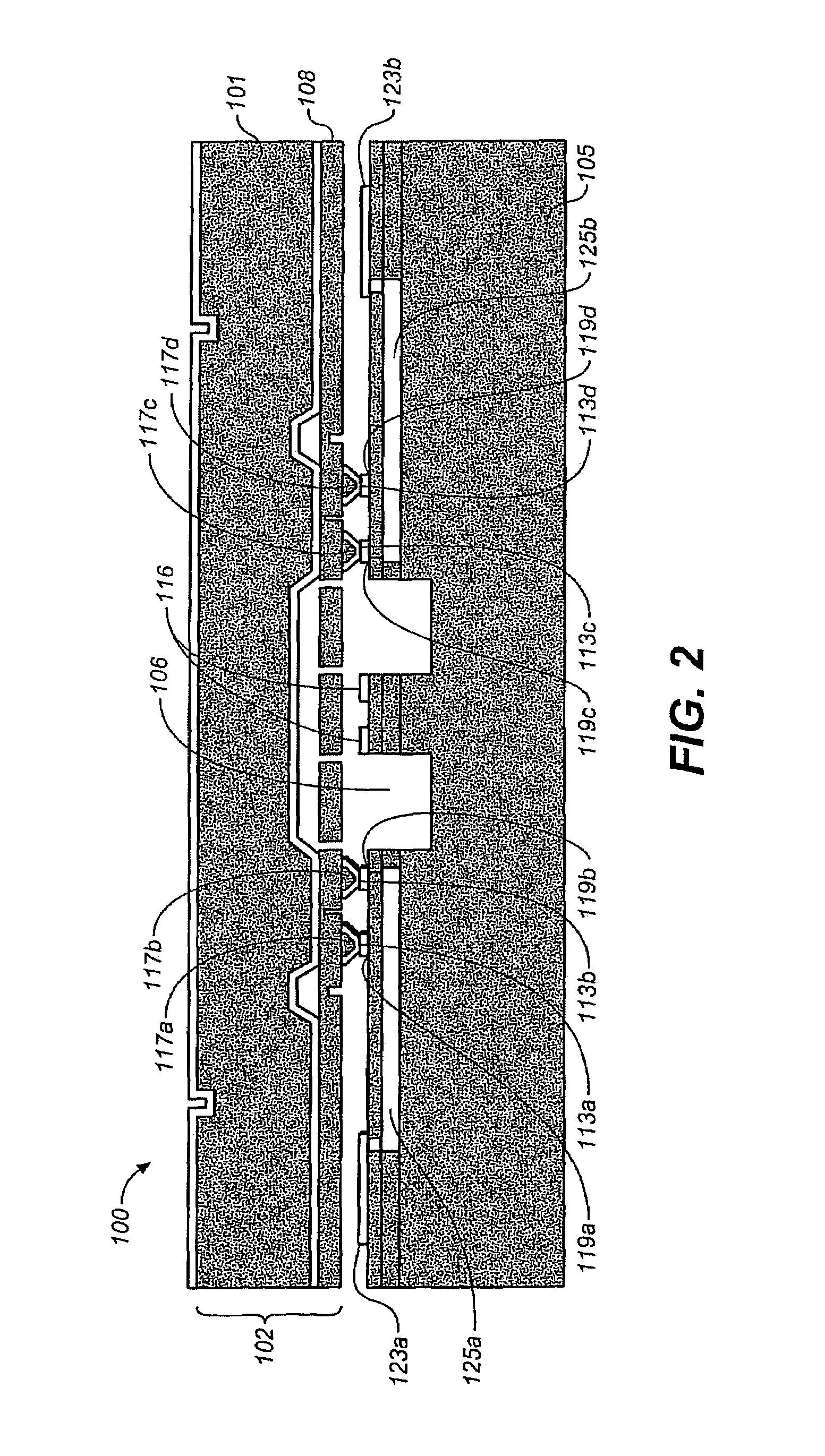
[0024]The following describes a preferred embodiment in accordance with the present invention. FIGS. 2A and 2B are cross sectional and top views of an assembly 100 in accordance with the present invention. Referring to the embodiment shown in FIG. 2A, a standard foundry CMOS wafer 104 which includes aluminum is bonded to a MEMS substrate 102 which includes germanium to provide an aluminum / germanium (Al / Ge) bond 110. In this embodiment, a cavity 106 is within the substrate 104. The CMOS substrate wafer 104 can be any substrate with patterned aluminum shown in FIG. 2B that is designed to interface with the MEMS substrate 102 to make for a complete functioning product. In addition, a plurality of aluminum contacts 116 are on the top of the CMOS substrate 104 which are coupled to bond pads 105 by interconnect 107. Vias 107 are provided in both the bond pads 105 and the aluminum contacts 116 to allow for electrical connection thereto. As an example, the substrate 104 can comprise only a ...
second embodiment
[0025]FIGS. 3A and 3B are cross sectional and top views of an assembly in accordance with the present invention. The assembly 200 includes many of the same elements as assembly 100 of FIG. 2 and those elements have the same reference numerals. Additionally, the assembly 200 has via contacts 202 through the MEMS substrate 102′ and the gap control standoff 111′ to provide electric feedthrough of signals.
[0026]Another important feature of the substrate 104 is the availability of the multilayer metallization standard in CMOS foundries with chemical-mechanical-polishing of the oxide to make for a very planar metallized layer suitable for forming Al / Ge eutectic alloy with a germanium presence on the MEMS layer. The MEMS substrate 102 can be a silicon wafer or combination of silicon wafers assembled with all the MEMS features and functionalities including any type of preprocessed features.
[0027]In the preferred embodiment, the MEMS substrate on which the germanium has been patterned is a s...
PUM
| Property | Measurement | Unit |
|---|---|---|
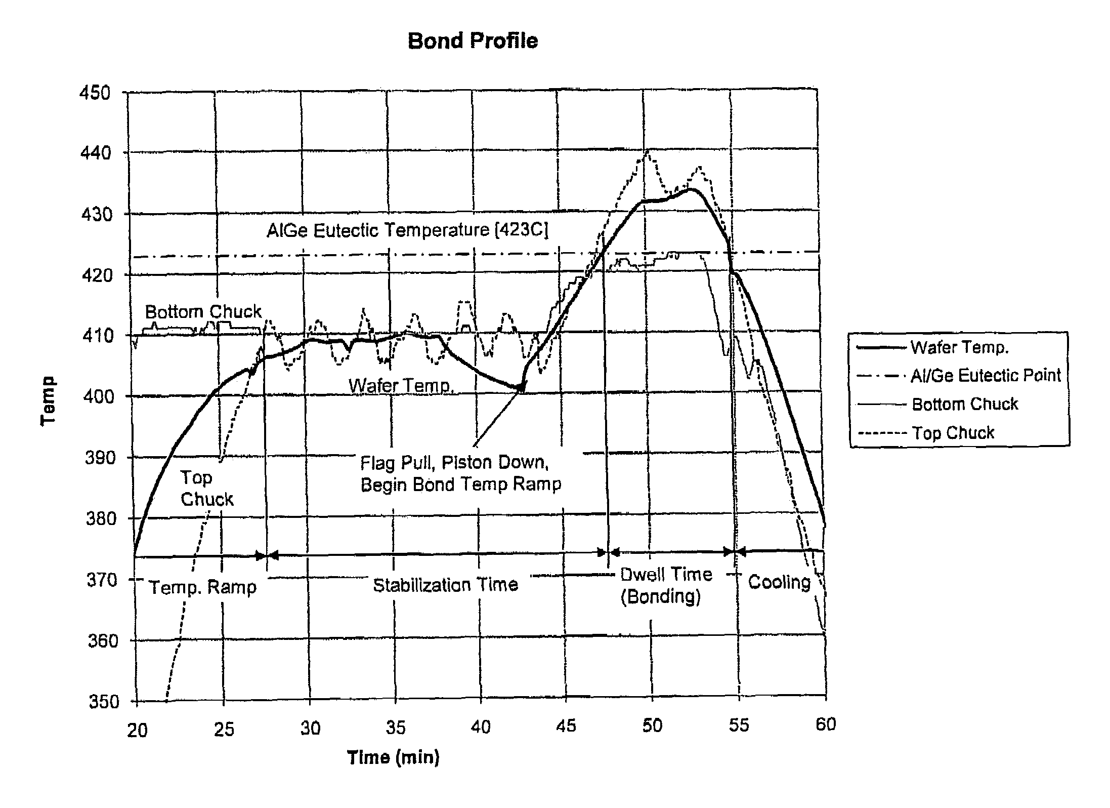
| temperature | aaaaa | aaaaa |
| temperature | aaaaa | aaaaa |
| temperature | aaaaa | aaaaa |
Abstract
Description
Claims
Application Information