
Method and the device for cryogenic therapy applied on the whole body of a patient

a cryogenic therapy and patient technology, applied in the field of cryogenic therapy on the whole body of the patient, can solve the problems of long starting time and needing a stand-by system, and achieve the effects of reducing heat loss, high efficiency, and reducing heat loss

Active Publication Date: 2012-04-24
METRUM CRYOFLEX SPOLKA Z ORGANICZONA ODPOWIEDZIALNOSCIA K
View PDF12 Cites 16 Cited by
  • Summary
  • Abstract
  • Description
  • Claims
  • Application Information

AI Technical Summary

Benefits of technology

[0007]The present invention provides a cryogenic chamber with means for producing a low temperature by vaporizing liquefied gas or a mixture of gases inside or outside the cryogenic chamber to provide a cold breathable atmosphere in the chamber. Preferably, the low temperature inside the cryogenic chamber is generated by vaporizing cold liquefied nitrogen and a cold liquefied oxygen or a mixture of cold liquefied nitrogen and a cold liquefied oxygen, for example cold liquefied air, wherein the mixture of gases is a mixture suitable for breathing. A cold gas is produced by vaporizing cold liquefied gases or a cold liquefied mixture of gases, preferable of a composition similar to air. Changing the proportions within the mixture or changing the flow rate of the supplied liquefied gas allows producing atmosphere of cold air with the enhanced amount of oxygen. The composition of the atmosphere inside the cryogenic chamber can be adjusted using simple means, in particular using a control system to selectively open and close valves for introducing the gas into the chamber. It is possible to establish an atmosphere of a defined composition, while the composition is maintained unchanged during the therapeutic session. However, it is also possible to modify the composition of the atmosphere during the therapeutic session. The invention allows therapy with a mixture specific gasses having periods of higher amount of oxygen inside the cryogenic chamber. The cryogenic chamber preferably allows patients to walk inside the chamber.
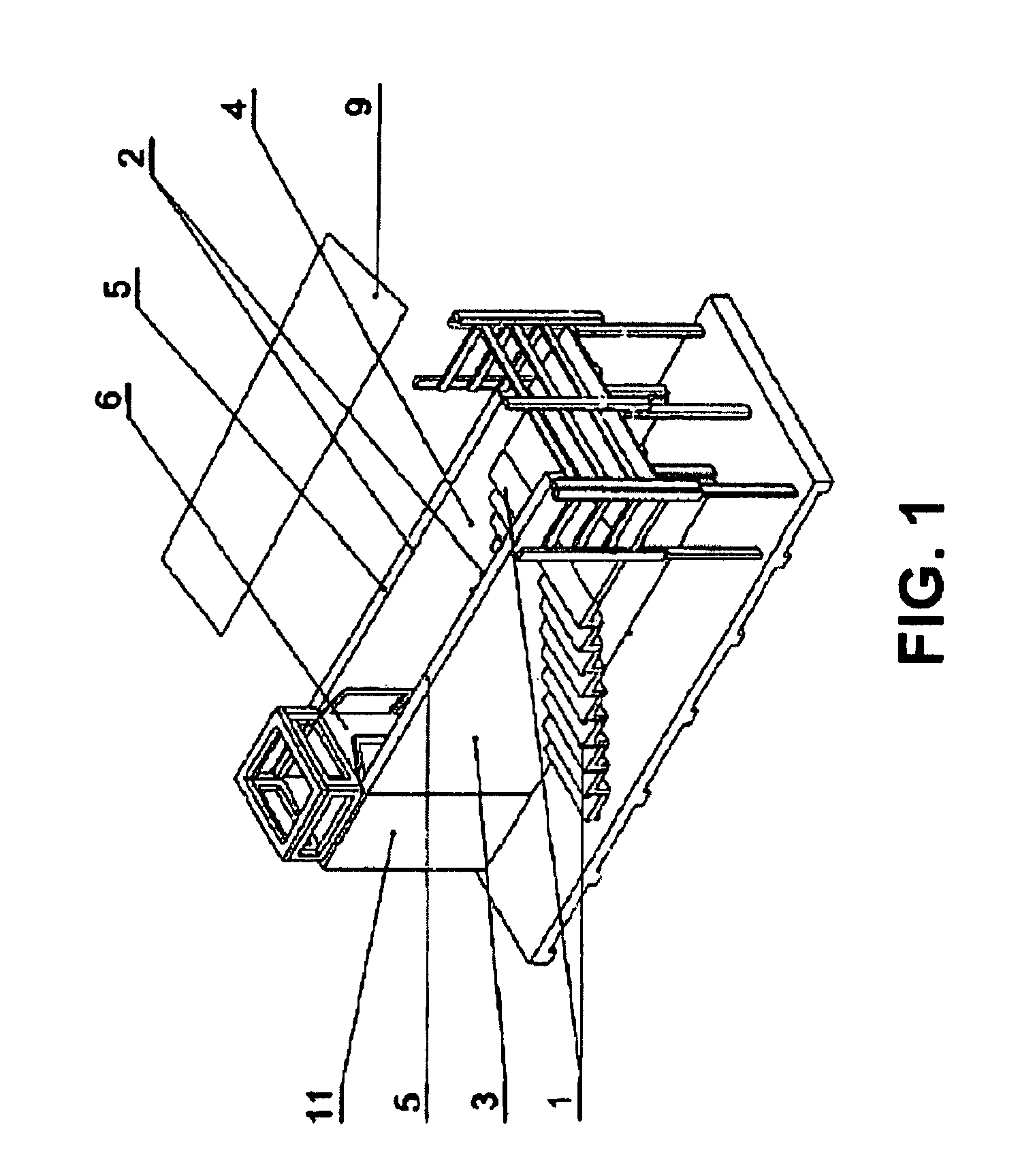
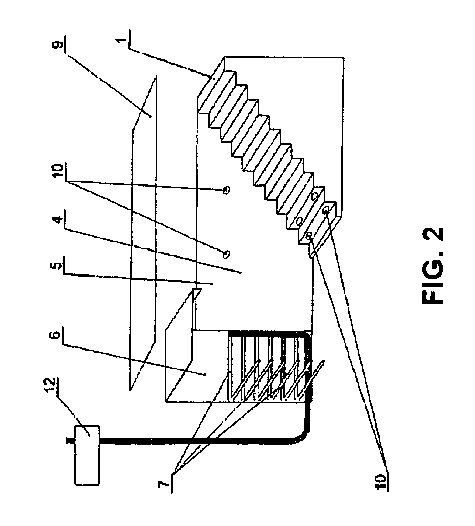
[0011]In another embodiment, the chamber has, in its upper part, a movable cover which is preferably transparent, and chamber lighting elements. The cryogenic therapeutic cabin can also includes an emergency door situated in a side wall of the chamber which enables the access to disabled patients on wheelchairs. The chamber may also include monitoring and control systems for temperature and oxygen concentration to maintain the proper temperature and oxygen levels, and to protect the patient or patients from temperature extremes and oxygen deprivation. If the temperature or oxygen concentration reaches beyond the safe limits, an alarm can be activated and the chamber operation can be shut down automatically.
[0012]The methods according to the invention provide proper and effective treatment for the patient; and the devices of the invention provides proper supply to the therapeutic chamber wherein the loaded gas has optimal parameters for the treatment regimen. The process is economical by taking advantage of the deposition of low temperature gas phenomenon.
[0014]It is advantageous to perform the cryogenic therapy, particularly on the whole body of the patient, according to the present invention because it allows for the correct treatment thanks to the preliminary cooling of the patient's body, which is conducted in the space in the chamber with the deposited low temperature cooling agent, after which the patient is introduced into the treatment cabin. After using the cabin, the patient is gradually led out to the normal temperature area through the space with the deposited low temperature cooling agent in the chamber.
[0015]It is advantageous to use the device for carrying out cryogenic therapy, particularly on the whole body of the patient, according to the present invention because it enables high efficiency by reducing the loss of heat while the patient enters and leaves the chamber through the upper part of the chamber, and limiting the space with the deposited low temperature cooling agent to the treatment chamber. The reduction of the loss of heat is obtained by using the movable transparent cover situated above the upper part of the chamber shielding it partially or completely while the patient or the patients are inside the cabin and when the cabin is empty. The lighting elements are situated in the internal surfaces of the chamber and allow for a comfortable environment for the patient. The emergency door situated in a side wall of the chamber also enables the direct exit of the patient from the cabin if needed.

Problems solved by technology

This device has several disadvantages, including long starting time and requiring a stand-by system.

Method used


Image

  • Method and the device for cryogenic therapy applied on the whole body of a patient
  • Method and the device for cryogenic therapy applied on the whole body of a patient
  • Method and the device for cryogenic therapy applied on the whole body of a patient

Examples


Embodiment Construction

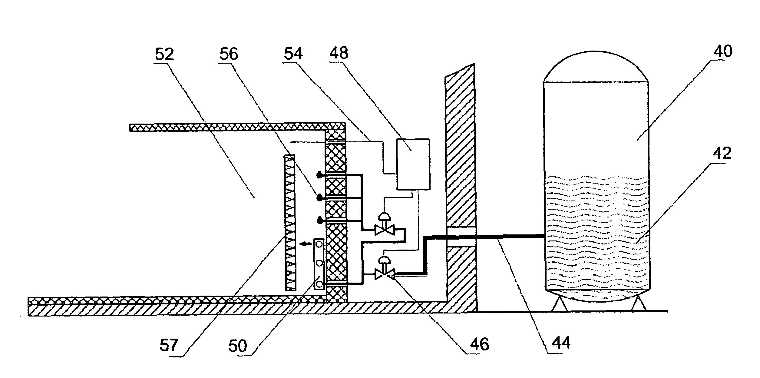
[0021]An embodiment of the present invention is shown in FIG. 4, where the device comprises a cryogenic chamber 52, preferably containing insulated walls. The chamber is cooled by a cooling agent 42 held in a tank 40. The mixture of gases preferably contains nitrogen and oxygen. Although FIG. 4 shows a single tank, each component of the cooling agent may be held separately and mixed in the chamber 52. In that case, there will be more than one tank, each holding a different component of the cooling agent. The cooling agent 42 is led into the chamber by a system of piping 44, valves, 46, heat exchanger 50, and nozzles 56. The nozzles 56 allow the gas to be vaporized by spraying to get the chamber more dynamic. Near the heat exchanger 50 there is a separating barrier 57 which separates the space in which treatment of a patient is carried out from the space in which the process of evaporation of liquefied gases occurs. This avoids directly contact of the patient with the gases in liquid...


PUM


Abstract

The present invention relates to methods and devices for carrying out cryogenic therapy, particularly on the whole body of a patient, wherein the patient is exposed to gases cooled to cryogenic temperature. The process is performed by introducing the patient into the interior of a treatment cabin and exposing the body to cold air deposited into the cabin space.

Description

[0001]This application is a continuation-in-part (CIP) of U.S. patent application Ser. No. 10 / 494,619, filed May 4, 2004, now U.S. Pat. No. 7,244,269 which is a U.S. National Phase of PCT / PL01 / 00087, filed Nov. 5, 2001.FIELD OF THE INVENTION[0002]The present invention relates to methods and the devices for carrying out the cryogenic therapy, particularly on the whole body of the patient, wherein the patient is exposed to the gases cooled to the cryogenic temperature. The process is performed by introducing the patient into the interior of the treatment cabin and exposing the body to the deposition of cold gases into the cabin space.BACKGROUND OF THE INVENTION[0003]There are known methods in medical technology for performing the cryogenic therapy by exposing certain parts of the human body or the whole body to the agents that reduces the temperature. These methods are generally carried out by using liquefied gases or compressed gases. Devices for carrying out the cryogenic treatment ...

Claims


Application Information

Patent Timeline
Patent Type & Authority Patents(United States)
IPC IPC(8): A61B18/02A61F7/00F25D3/10
CPCA61F7/0053F25D3/102
Inventor BROJEK, WIESLAWSZMURLO, WLODZIMIERZ
Owner METRUM CRYOFLEX SPOLKA Z ORGANICZONA ODPOWIEDZIALNOSCIA K
Learn More