Thermal capsulotomy tool and system

a technology of capsulotomy and tool, applied in the field of cataract surgery, can solve the problems of increased likelihood of vitreous entry into the anterior chamber, loss of structural stability of the capsule, and difficulty in controlling the procedure of the surgeon

Active Publication Date: 2012-04-24
VALENS ASSOC INC
View PDF14 Cites 24 Cited by
  • Summary
  • Abstract
  • Description
  • Claims
  • Application Information

AI Technical Summary

Benefits of technology

[0015]Accordingly, it is a principal object of the present invention to provide a thermal system and tool for the performance of a capsulotomy that effects formation of an opening in the lens capsule through the use of a short pulse of electrical current. The heat generated from the current instantaneously burns an opening of a predetermined size in the lens capsule.

Problems solved by technology

Unfortunately, when opening the capsule with numerous small capsular tears, the small tags that remain become a focal area of least resistance and can lead to tears, which extend radially and posteriorly to the posterior capsule.
The detrimental result is a loss of structural stability of the capsule and an increased likelihood of vitreous entry into the anterior chamber.
This procedure is challenging for the surgeon to control.
The tearing motion can lead to an undesirable tear toward the equator and the posterior capsule, and the size of the opening is difficult to dictate.
Opening the anterior capsule via either of the described techniques of anterior capsulotomy is a delicate procedure and is widely considered to be one of the most difficult steps in cataract surgery.
A poorly performed anterior capsulotomy significantly hinders the subsequent surgical steps and increases the probability of operative complications.
Complications resulting from a poor capsulotomy include zonular stress with subsequent breakage of the posterior capsule, vitreous loss, and large capsular tags preventing efficient lens removal.
A poor capsulotomy also prevents placement of an intraocular lens in the capsular bag) due to ill-defined capsular structures.
The operative time is lengthened and patient discomfort can be increased, along with the risk of postoperative complications and decreased visual acuity results.
With either of the above-described techniques for anterior capsulotomy, the size or position of the capsular opening is often not ideal.
For example, an overly small capsular opening can impair the safe removal of the lens nucleus and cortex and prevent proper intraocular lens insertion into the lens capsule.
In addition, a small or eccentric capsular opening places excessive stress on the lens capsule during surgery, placing the eye at risk for zonular and capsular breakage.
However, use of such devices in small incision cataract surgery is limited due to their size.
The use of prior art burning tools is restricted by the small size of the incision, as previously mentioned, which hampers introduction of a large tip having a circular shape of the appropriate size of the desired seared area.
The Sheffer patent suffers from the disadvantage that the burning ring does not close a complete circle, as apparent in FIG. 1b, with the area near the handle not being seared.
Therefore, it is still necessary to grasp that remaining area with a forceps, and form a tear that is difficult to control.
Additionally, since the searing ring is formed from a single metal wire extending substantially into the depths of the handle, when the wire is heated electrically, it is difficult to insulate the tool and prevent heating in unwanted areas.
Searing could accidentally occur in other portions of the eye adjacent to the lens, since the handle of the tool could heat, and since the tool needs to be inserted considerably into the eye.
It is difficult to manipulate the burning tool to form a series of burns that are reliably ring-shaped and are present at the desired location, and form a ring of the desired size.
Additionally, in cataract surgery, the procedure is usually complicated by the need for multiple instruments: a cutting tool, an air pressure inlet, a water pressure inlet, and related surgical and electrical equipment.

Method used


Image

  • Thermal capsulotomy tool and system
  • Thermal capsulotomy tool and system
  • Thermal capsulotomy tool and system

Examples


Embodiment Construction

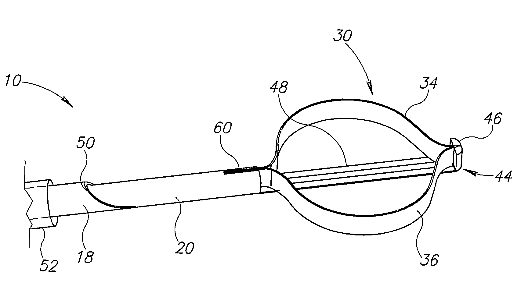
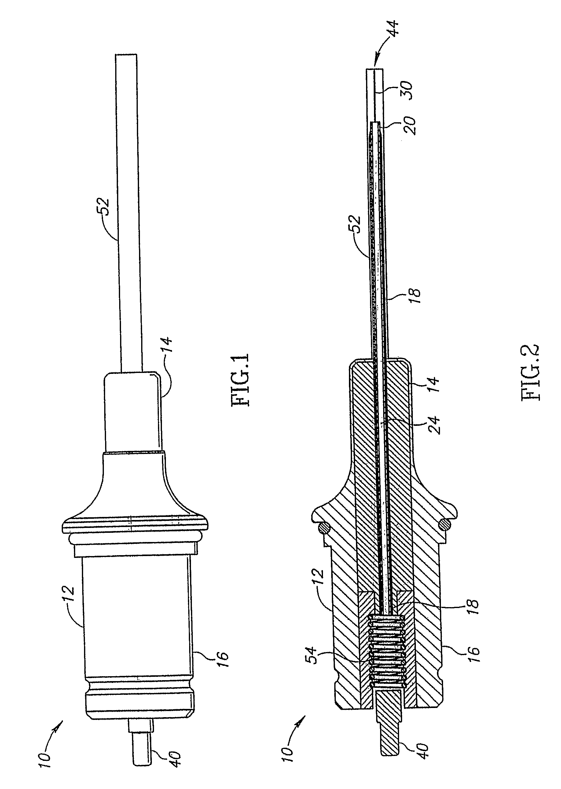
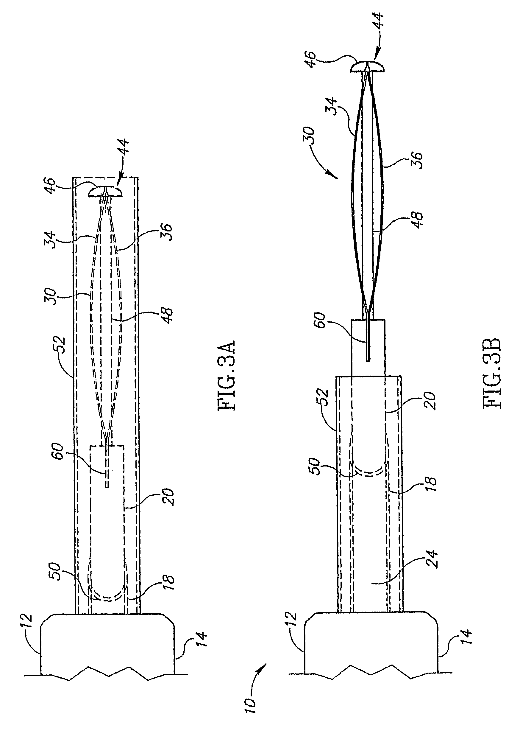
[0044]The present invention discloses a capsulotomy tool, which has a retractable cautery ring, also known as a burning element. The burning element is initially hidden within a sleeve. After the tool is inserted past the capsular incision, the burning element is progressively extended from within the sleeve by sliding outwards several concentrically arranged tubes with which the element is associated. Finally, the burning element is fully opened to expand into a complete circular or complete oval shaped cautery, which is then heated to sear the lens. The complete circular or oval-shaped searing thus eliminates the need for tearing by forceps, which is potentially dangerous and difficult to perform.

[0045]In the invention, heating is limited to the burning element, so there is no danger of searing inappropriate areas of the eye. The retractable nature of the burning element allows it to be introduced through a small capsular incision, yet provides burning on the lens at a diameter la...


PUM


Abstract

A system and tool for performing a capsulotomy procedure. The system includes an air pressure unit providing pressurized airflow, a capsulotomy and movement control unit providing electrical current and movement control, and a capsulotomy tool including a main housing, and an extendable-retractable burning element coupled to the main housing. The tool is in connection with the capsulotomy and movement control unit for providing electrical current to the burning element and movement control for extending and retracting the burning element. When the burning element is in a flattened, retracted configuration, the tip of the tool can be inserted through a relatively small corneal incision. Once in the anterior chamber, the burning element is switched to a circular, extended configuration, so as to allow performance of a capsulotomy by applying an electrical pulse to the burning element.

Description

FIELD OF THE INVENTION[0001]The present invention relates to generally to the field of cataract surgery. More specifically, the present invention relates to a thermal tool and system for burning a relatively large round thermal capsulotomy through a relatively small corneal incision. The system provides heat, and airflow, to the surgical site such that the capsulotomy can be performed with efficiency and ease.BACKGROUND OF THE INVENTION[0002]To date, over one million cataract surgeries are performed annually in the United States, in which the anterior lens capsule must be opened to gain access to the lens nucleus and allow removal of degenerated cortical material. It is necessary to create a relatively large circular opening in the lens capsule in order to enter the lens interior and to withdraw matter from inside. Formation of this opening is known as a capsulotomy. It is important that the opening has smooth edges and is tear resistant so that the lens contents can be easily remov...

Claims


Application Information

Patent Timeline
Patent Type & Authority Patents(United States)
IPC IPC(8): A61B18/08
CPCA61B18/08A61F9/00754
Inventor BEN-NUN, JOSHUA
Owner VALENS ASSOC INC
Why Eureka
Try Eureka