Method for adjusting engine air-fuel ratio

a technology of air-fuel ratio and engine, which is applied in the direction of electrical control, process and machine control, instruments, etc., can solve the problems of undesirable disturbance of the amplitude and/or frequency of the post catalyst oxygen sensor output, the output of the post catalyst oxygen sensor is somewhat difficult to converge to the time, and the efficiency of the catalyst may degrade, etc., to reduce the regulated engine emission, promote catalyst efficiency, and reduce the catalyst light off time

Active Publication Date: 2012-04-24
FORD GLOBAL TECH LLC
View PDF17 Cites 6 Cited by
  • Summary
  • Abstract
  • Description
  • Claims
  • Application Information

AI Technical Summary

Benefits of technology

[0002]Catalysts are commonly coupled to engine exhaust systems for reducing regulated engine emissions. The catalysts may be configured with different coatings to promote catalyst efficiency and reduce catalyst light off time (e.g., the amount of time it takes for a catalyst to reach a predetermined efficiency). However, even with higher performance catalyst coatings, it can be important to control engine exhaust gases entering the catalyst or the catalyst efficiency may degrade.
[0003]In U.S. Pat. No. 6,591,605 catalyst efficiency may be improved by adjusting engine air-fuel ratio via feedback from a combination of a time varying signal and an output of a post catalyst oxygen sensor. However, if there is an error between the output of the post catalyst oxygen sensor and the time varying signal, a single error adjustment term simultaneously accounts for errors in amplitude, phase, and frequency. As a result, adjusting the engine air-fuel ratio for a phase error in the post catalyst oxygen sensor output may cause an undesirable disturbance in the amplitude and / or frequency of the post catalyst oxygen sensor output. Consequently, it may be somewhat difficult for the output of the post catalyst oxygen sensor to converge to the time varying signal during some operating conditions.
[0005]By adjusting an air-fuel ratio supplied to an engine via frequency and duty cycle adjustments, it may be possible for an output of a post catalyst oxygen sensor to converge to a desired response at a faster rate. In particular, when individual adjustments are made to an engine air-fuel ratio for frequency errors and / or duty cycle errors between the output of a post catalyst oxygen sensor and a predetermined signal, it may be possible to compensate for the errors with less affect on other signal attributes.
[0006]The present description may provide several advantages. Specifically, the approach may improve catalyst conversion efficiency. In addition, the approach may provide more consistent vehicle emissions since duty cycle errors can be compensated separately from frequency errors. Further, the approach provides for duty cycle and frequency adjustments for a broad range of operating conditions beyond basic engine operating conditions.

Problems solved by technology

However, even with higher performance catalyst coatings, it can be important to control engine exhaust gases entering the catalyst or the catalyst efficiency may degrade.
However, if there is an error between the output of the post catalyst oxygen sensor and the time varying signal, a single error adjustment term simultaneously accounts for errors in amplitude, phase, and frequency.
As a result, adjusting the engine air-fuel ratio for a phase error in the post catalyst oxygen sensor output may cause an undesirable disturbance in the amplitude and / or frequency of the post catalyst oxygen sensor output.
Consequently, it may be somewhat difficult for the output of the post catalyst oxygen sensor to converge to the time varying signal during some operating conditions.

Method used


Image

  • Method for adjusting engine air-fuel ratio
  • Method for adjusting engine air-fuel ratio
  • Method for adjusting engine air-fuel ratio

Examples


Embodiment Construction

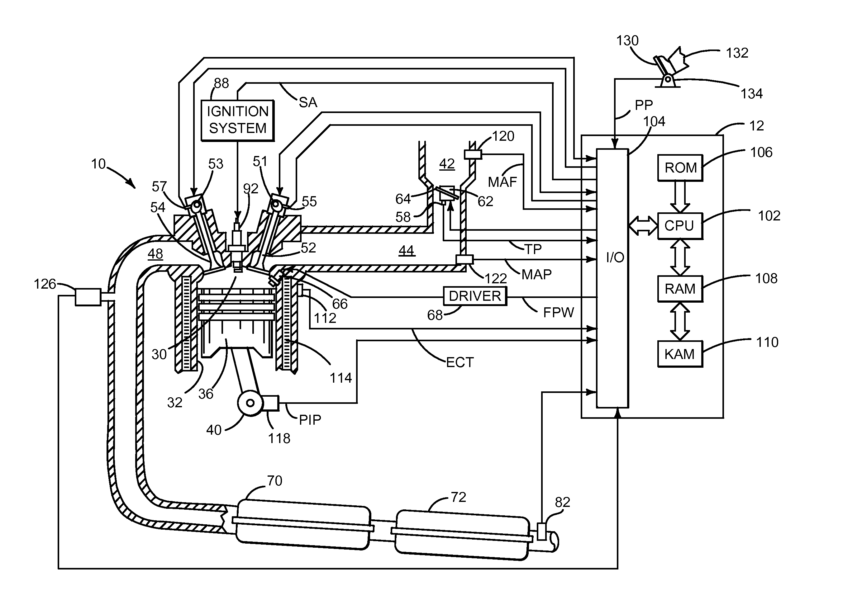
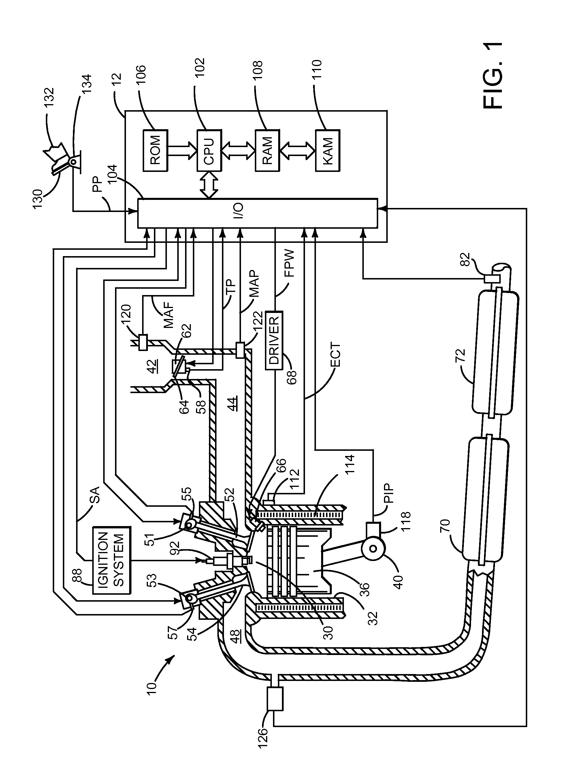
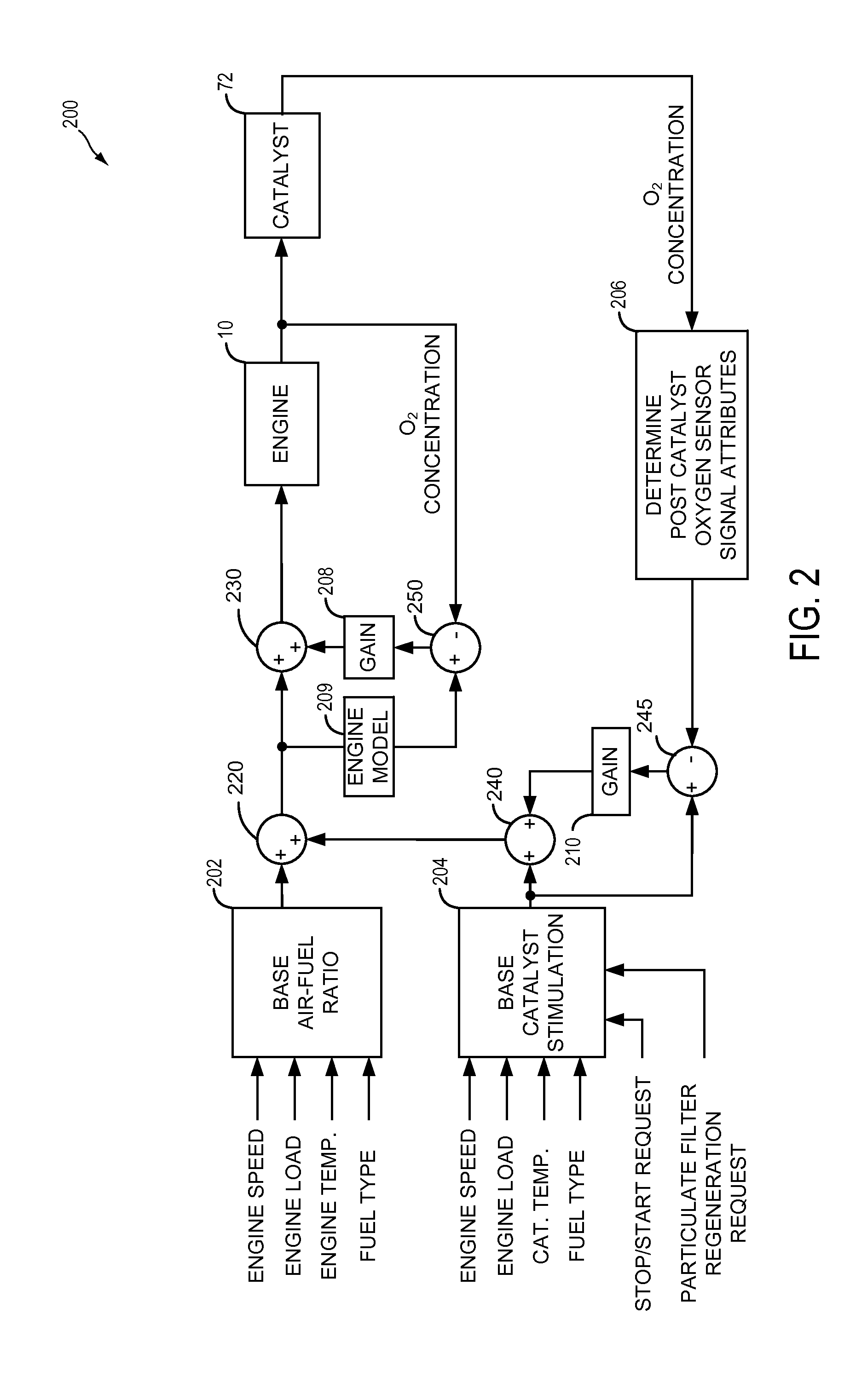
[0014]The present description is related to adjusting an engine air-fuel ratio. In one non-limiting example, the engine may be configured as part of the system illustrated in FIG. 1. The engine air-fuel ratio may be adjusted via a controller as illustrated in FIG. 2. The system of FIG. 1 and the controller of FIG. 2 may combine to provide the signals illustrated in FIG. 3. The signals of FIG. 3 show how engine air fuel may be adjusted and how duty cycle and frequency information can be derived from output of a post catalyst oxygen sensor. FIG. 4 shows a method to adjust engine air-fuel ratio via executable instructions of the controller illustrated in FIG. 1.

[0015]Referring now to FIG. 1, internal combustion engine 10, comprising a plurality of cylinders, one cylinder of which is shown in FIG. 1, is controlled by electronic engine controller 12. Engine 10 includes combustion chamber 30 and cylinder walls 32 with piston 36 positioned therein and connected to crankshaft 40. Combustion...


PUM


Abstract

A method for adjusting an air-fuel ratio of an engine is disclosed. In one example, the engine air-fuel ratio is adjusted in response to a duty cycle and frequency of a post catalyst oxygen sensor. The method may improve catalyst efficiency.

Description

FIELD[0001]The present description relates to a method and system for adjusting engine air-fuel ratio. The method may be particularly useful for engines that include one or more catalysts located in an exhaust system of the engine.BACKGROUND AND SUMMARY[0002]Catalysts are commonly coupled to engine exhaust systems for reducing regulated engine emissions. The catalysts may be configured with different coatings to promote catalyst efficiency and reduce catalyst light off time (e.g., the amount of time it takes for a catalyst to reach a predetermined efficiency). However, even with higher performance catalyst coatings, it can be important to control engine exhaust gases entering the catalyst or the catalyst efficiency may degrade.[0003]In U.S. Pat. No. 6,591,605 catalyst efficiency may be improved by adjusting engine air-fuel ratio via feedback from a combination of a time varying signal and an output of a post catalyst oxygen sensor. However, if there is an error between the output of...

Claims


Application Information

Patent Timeline
Patent Type & Authority Patents(United States)
IPC IPC(8): F02D41/30F01N3/00
CPCF02D41/0235F02D41/1401F02D41/1441F02D41/1454F02D41/042F02D41/1456F02D2041/1419F02D2041/1422F02D2041/1437F02D2200/0802
Inventor REED, DENNIS CRAIGANDERSON, BRUCE COLBY
Owner FORD GLOBAL TECH LLC
Why Eureka
Try Eureka