
Gas turbine engine airfoil

a gas turbine engine and air filter technology, applied in the direction of liquid fuel engines, marine propulsion, vessel construction, etc., can solve the problems of gas turbine engine performance loss, negative impact on stall margin, and reduced compressor section pressure rise ability

Active Publication Date: 2012-05-01
RTX CORP
View PDF18 Cites 62 Cited by
  • Summary
  • Abstract
  • Description
  • Claims
  • Application Information

AI Technical Summary

Problems solved by technology

Tip clearance flow reduces the ability of the compressor section to sustain pressure rise and may have a negative impact on stall margin (i.e., the point at which the compressor section can no longer sustain an increase in pressure such that the gas turbine engine stalls).
Airflow escaping through the gaps between the rotor blades and the shroud can create gas turbine engine performance losses.
Disadvantageously, prior rotor blade airfoil designs have not adequately alleviated the negative effects caused by tip clearance flow.

Method used


Image

  • Gas turbine engine airfoil
  • Gas turbine engine airfoil
  • Gas turbine engine airfoil

Examples


Embodiment Construction

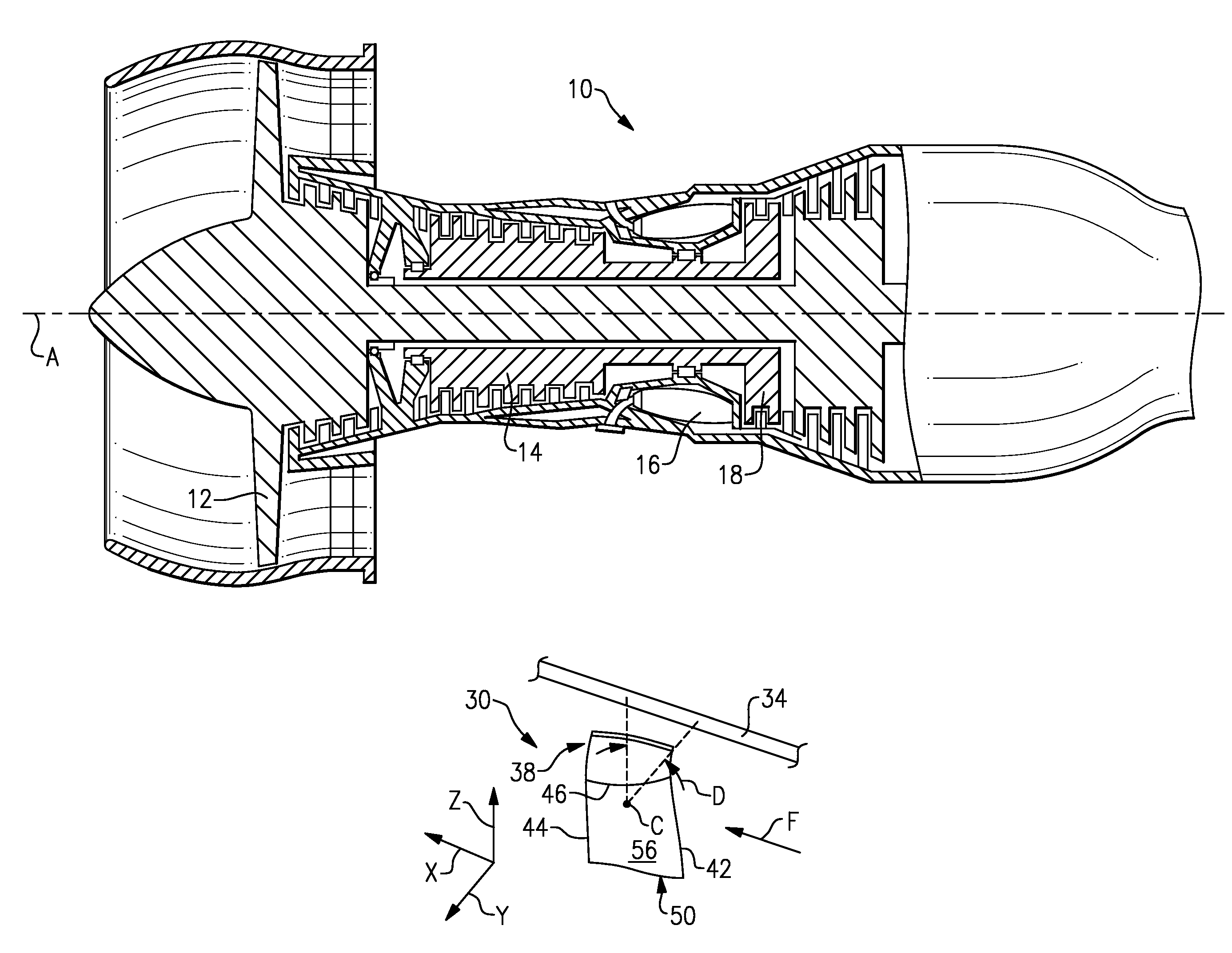
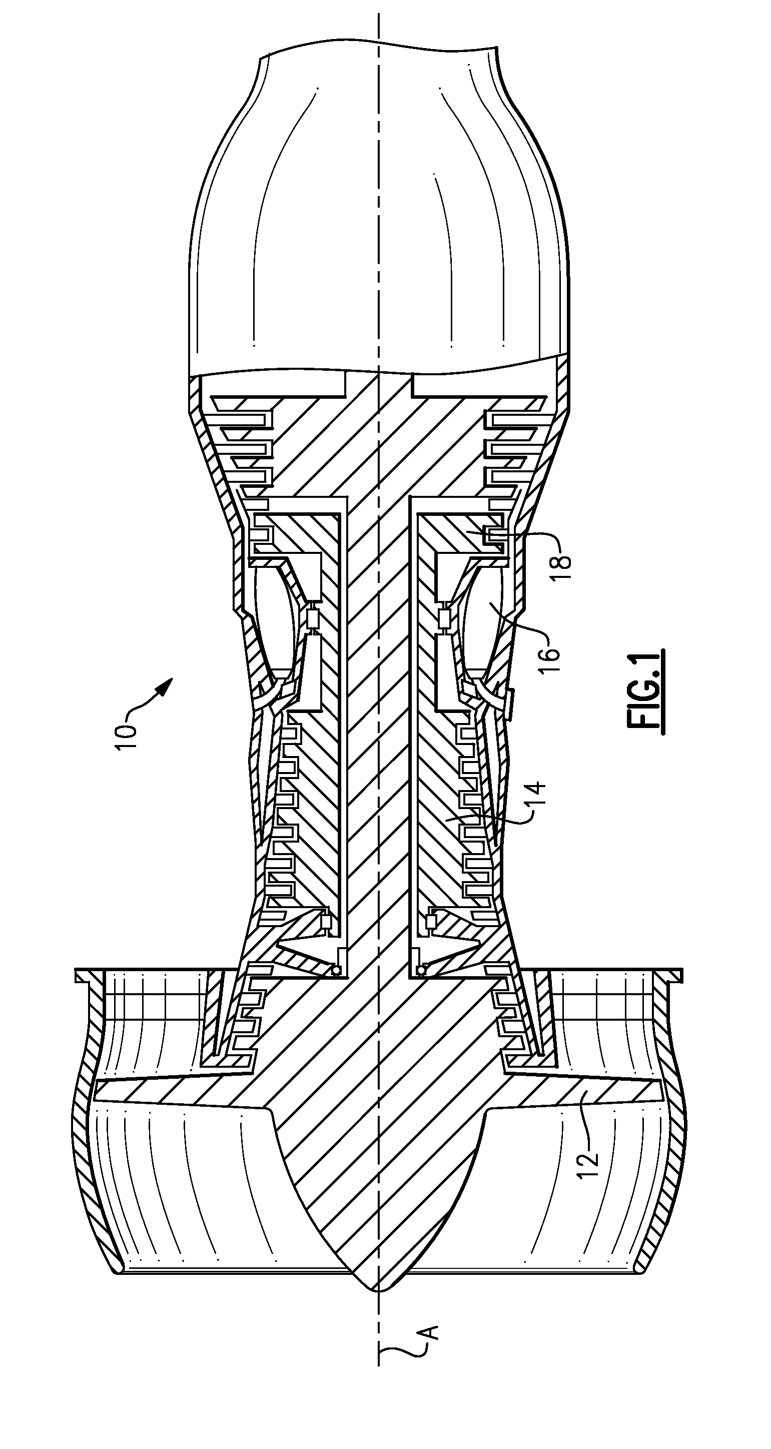
[0017]FIG. 1 illustrates an example gas turbine engine 10 that includes a fan12, a compressor section 14, a combustor section 16 and a turbine section 18. The gas turbine engine 10 is defined about an engine centerline axis A about which the various engine sections rotate. As is known, air is drawn into the gas turbine engine 10 by the fan 12 and flows through the compressor section 14 to pressurize the airflow. Fuel is mixed with the pressurized air and combusted within the combustor 16. The combustion gases are discharged through the turbine section 18 which extracts energy therefrom for powering the compressor section 14 and the fan 12. Of course, this view is highly schematic. In one example, the gas turbine engine 10 is a turbofan gas turbine engine. It should be understood, however, that the features and illustrations presented within this disclosure are not limited to a turbofan gas turbine engine. That is, the present disclosure is applicable to any engine architecture.

[0018...


PUM

PropertyMeasurementUnit
sweep angleaaaaaaaaaa
dihedral angleaaaaaaaaaa
energyaaaaaaaaaa

Abstract

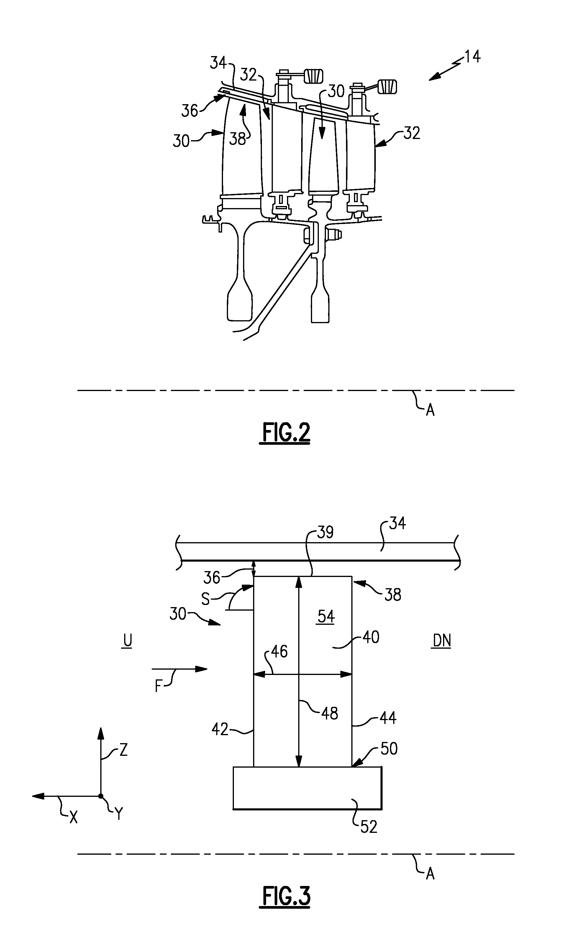
A rotor blade for a gas turbine engine includes an airfoil that extends in span between a root and a tip region. A leading edge and a trailing edge of the airfoil section extend between a chord line of the airfoil. A sweep angle is defined at the leading edge of the airfoil section, and a dihedral angle is defined relative to the chord line of the airfoil section. The sweep angle and the dihedral angle are localized at the tip region of the airfoil section.

Description

BACKGROUND OF THE DISCLOSURE[0001]This disclosure generally relates to a gas turbine engine, and more particularly to rotor blades that improve gas turbine engine performance.[0002]Gas turbine engines, such as turbofan gas turbine engines, typically include a fan section, a compressor section, a combustor section and a turbine section. During operation, air is pressurized in the compressor section and mixed with fuel in the combustor section for generating hot combustion gases. The hot combustion gases flow through the turbine section which extracts energy from the hot combustion gases to power the compressor section and drive the fan section.[0003]Many gas turbine engines include axial-flow type compressor sections in which the flow of compressed air is parallel to the engine centerline axis. Axial-flow compressors utilize multiple stages to obtain the pressure levels needed to achieve desired thermodynamic cycle goals. A typical compressor stage consists of a row of moving airfoil...

Claims


Application Information

Patent Timeline
Patent Type & Authority Patents(United States)
IPC IPC(8): B63H1/26B63H7/02
CPCF01D5/12F04D29/324F01D5/141Y10T29/49336Y10T29/49337Y10T29/49321F05D2240/301
Inventor KIRCHNER, JODYDONG, YUANHINGORANI, SANJAY S.
Owner RTX CORP
Learn More