Expandable dental implants of high surface area and methods of expanding the same

a dental implant and high surface area technology, applied in dental implants, dental surgery, prosthesis, etc., can solve the problems of improper drilling of the bore, bone resorption, and patients' disassembly and maintenance,

Active Publication Date: 2012-05-01
DENTACK IMPLANTS
View PDF21 Cites 12 Cited by
  • Summary
  • Abstract
  • Description
  • Claims
  • Application Information

AI Technical Summary

Benefits of technology

[0044]A portion of the envelope is expanded from a contracted position to an expanded position by moving the expander member within the barrel along the longitudinal axis from the first region to the second region. A portion of the expander is secured with the barrier thereby prohibiting the expander from moving from the second region toward the first region.
[0046]It is hence one object of the present invention to disclose a self-contained expandable implant (100), comprising: (a) a threadless elongated envelope (1) spanning along a main longitudinal axis (H); transformable from an initial contracted configuration to an expanded configuration; (b) at least one threadless conical expander (20) longitudinally displaceable within the envelope (1) from a coronal position to an apical position or vice versa; such that the expander is thrusted by a pusher along the main longitudinal axis, the expander is tightly fitted into the envelope in a singular predetermined position; wherein the expander is forcefully yet not rotatably immobilized by a lock mechanism integrally incorporated within the envelope; and further wherein the combination of the envelope (1) module and the expander (20) modules is sufficient to secure the implant (100) in the expanded configuration. This implant may be especially adapted for short implants preferably of about 5 to 16 mm. The fact that the immobilizing mechanism is one with the implant's envelope and lies within the radial horizontal plane of the envelope, allows further to develop short implants as detailed above. Thus, this short implant may further especially be adapted to be implanted in thin-walled or deformed jawbones. The expandable implant (100) has a coronal portion attachable to a prosthetic piece.
[0049]It is in the scope of the present invention implant to teach that the expander (20) is displaced along the main longitudinal axis of envelope (1) in a vertical manner. It is further in the scope of the present invention implant to teach that the expander (20) expands the apical portion of the envelope (1). During the implant's expansion the slits (4) are at least partially uncovered by the lids (5). The slits (4) may be at least partially uncovered by the lids (5) in a discrete manner. The exposure of covered parts of the slits may expand the envelope's surface area into the expanded surface S1.
[0056]It is a fifth object of the present invention to disclose a method for securing an expandable implant within a jawbone that comprises; obtaining a self-contained expandable implant (100) with (i) threadless elongated envelope (1) spanning along a main longitudinal axis (H), transformable from an initial contracted configuration to an expanded configuration; and, (ii) at least one threadless conical expander (20) displacing longitudinally within the envelope (1) from a first coronal position to a second apical position or vice versa; such that the thrusting of expander apically by a pusher along the main longitudinal axis tightly fits the expander into the envelope in a singular predetermined position; wherein immobilizing the expander is forcefully, yet not rotatably, by a lock mechanism integrally incorporated within the envelope and further wherein the combination of the envelope (1) module and the expander (20) modules is sufficient to secure the implant (100) in the expanded configuration. Adapting the implant especially for short implants preferably of about 5 to 16 mm. Further adapting the implant to be implanted in thin-walled or deformed jawbones. The fact that the immobilizing mechanism is one with the implant's envelope and lies within the radial horizontal plane of the envelope, allows further to develop short implants as detailed above. The expandable implant (100) having a coronal portion attachable to a prosthetic piece.

Problems solved by technology

The prosthetic piece may not be received in the implant for a period of approximately five months, until bone tissue of the jawbone grows and eventually fuses with the implant, causing discomfiture to a patient and necessitating several visits to an oral surgeon.
During this period, bone resorption is noticeable, due to the lack of pressure normally applied by the extracted tooth onto the bone tissue.
At times, the bore is improperly drilled, and is much larger than the fixed diameter of the implant.
As a result, the implant will not be properly secured to the jawbone.
Micro-movement of the implant relative to the wall of the bore is another cause of implant looseness.
The slits reduce the available barrel surface area that engages the sidewall of the bore, and also weaken the structure of the implant.
Furthermore, the exterior surface of the barrel, which is not immobilized, is liable to be loosened from the sidewall of the jawbone bore over the course of time.
Since the expander screw mates with the threading formed on the interior surface of the barrel, reverse rotation of the expander screw, i.e. in a rotational direction opposite to that which causes the barrel to press into the sidewall of the jawbone, due to inter-jaw dynamic compressive forces and fluctuating stresses, results in a loosening of the implant.

Method used


Image

  • Expandable dental implants of high surface area and methods of expanding the same
  • Expandable dental implants of high surface area and methods of expanding the same
  • Expandable dental implants of high surface area and methods of expanding the same

Examples


Embodiment Construction

[0063]The following description is provided, alongside all chapters of the present invention, so as to enable any person skilled in the art to make use of the invention and sets forth the best modes contemplated by the inventor of carrying out this invention. Various modifications, however, will remain apparent to those skilled in the art, since the generic principles of the present invention have been defined specifically to provide expandable dental implants of high surface area and to methods of expanding and anchoring the same in situ.

[0064]The term “longitudinal” refers hereinafter to the direction of the long axis or “top-to-bottom” axis.

[0065]The term “apical” refers hereinafter to the direction of the dental root or oral cavity.

[0066]The term “coronal” refers hereinafter to the direction of the crown of the tooth.

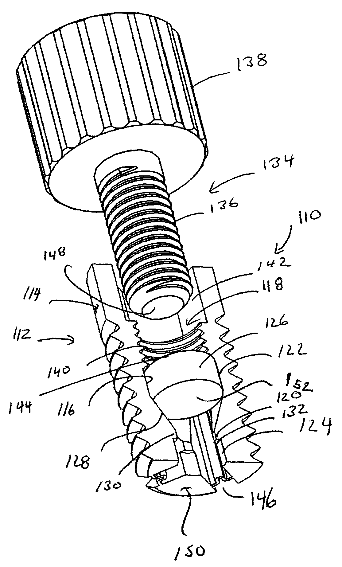
[0067]The term “expandable” refers hereinafter to the capability of the implant to increase its lateral dimension.

[0068]The term “expander” refers hereinafter to an...


PUM


Abstract

A dental implant system for placement within a jaw of a patient includes an envelope including an outer surface and an inner surface defining a barrel. At least one barrier is located in the barrel. The barrel having a first region on one side of the barrier and a second region on an opposing side of the barrier. An expander member is movable within the barrel along a longitudinal axis of the barrel from the first region to the second region. The barrier prohibits the expander member from moving from the second region to the first region.

Description

RELATED APPLICATION[0001]The present application claims priority under Article 8 of the Patent Cooperation Treaty to Israeli Patent Application No. 177848 filed Sep. 3, 2006 entitled “Expandable Dental Implants of High Surface Area and Methods of Expanding Same” incorporated herein in its entirety by reference.FIELD OF THE INVENTION[0002]The present invention pertains to expandable dental implants of high surface area and to methods of in situ expanding the same.BACKGROUND OF THE INVENTION[0003]Endosseous root form implants—hereinafter referred to as “implants”—are well known devices, which are adapted to support and receive dental prosthetic pieces. Root form implants are generally cylindrical, with a surface area designed to promote good attachment to the jawbone. Most implants are made of titanium or of a titanium alloy, due to the biocompatibility and high rate of osseointegration, i.e. the physiological process of fusing with a living bone, of such a material.[0004]Non-expandab...

Claims


Application Information

Patent Timeline
Patent Type & Authority Patents(United States)
IPC IPC(8): A61C8/00
CPCA61C8/0033A61C8/0039A61C8/0089A61C8/00A61C13/10
Inventor VACHTENBERG, OZ
Owner DENTACK IMPLANTS
Why Eureka
Try Eureka