Low voltage drop closed loop unidirectional electronic valve

a closed loop, electronic valve technology, applied in the direction of valve operating means/release devices, pv power plants, pulse techniques, etc., can solve the problems of reverse voltage build-up across solar panels, loss to the system,

Active Publication Date: 2012-05-01
MICROSEMI CORP
View PDF12 Cites 109 Cited by
  • Summary
  • Abstract
  • Description
  • Claims
  • Application Information

AI Technical Summary

Benefits of technology

[0009]Accordingly, it is a principal object of the present invention to overcome the disadvantages of prior art unidirectional electronic valves. This is provided in certain embodiments by a unidirectional electronic valve comprising an electronically controlled switch, such as a MOSFET, arranged to connect between a first terminal and a second terminal. A first charge pump is further provided and arranged to close the first electronically controlled switch when the voltage potential at the first terminal is greater than the voltage potential at the second terminal by a first value. The first charge pump is arranged in a closed loop with the first electronically controlled switch so as to continuously maintain the voltage potential at the first terminal greater than the voltage potential at the second terminal by the first value. Advantageously, a reverse voltage potential of about 50 millivolts is continuously provided when the solar panel is in a shaded condition.

Problems solved by technology

The power lost to the system is emitted as heat, which thus drives thermal considerations for panel layout, construction of bypass diode 20 and ultimately cost of the arrangement of FIG. 1.
The requirement for the periodic opening of the switch leads to a reverse voltage build up across the solar panel which is undesirable.

Method used


Image

  • Low voltage drop closed loop unidirectional electronic valve
  • Low voltage drop closed loop unidirectional electronic valve
  • Low voltage drop closed loop unidirectional electronic valve

Examples


Embodiment Construction

[0024]Before explaining at least one embodiment of the invention in detail, it is to be understood that the invention is not limited in its application to the details of construction and the arrangement of the components set forth in the following description or illustrated in the drawings. The invention is applicable to other embodiments or of being practiced or carried out in various ways. Also, it is to be understood that the phraseology and terminology employed herein is for the purpose of description and should not be regarded as limiting.

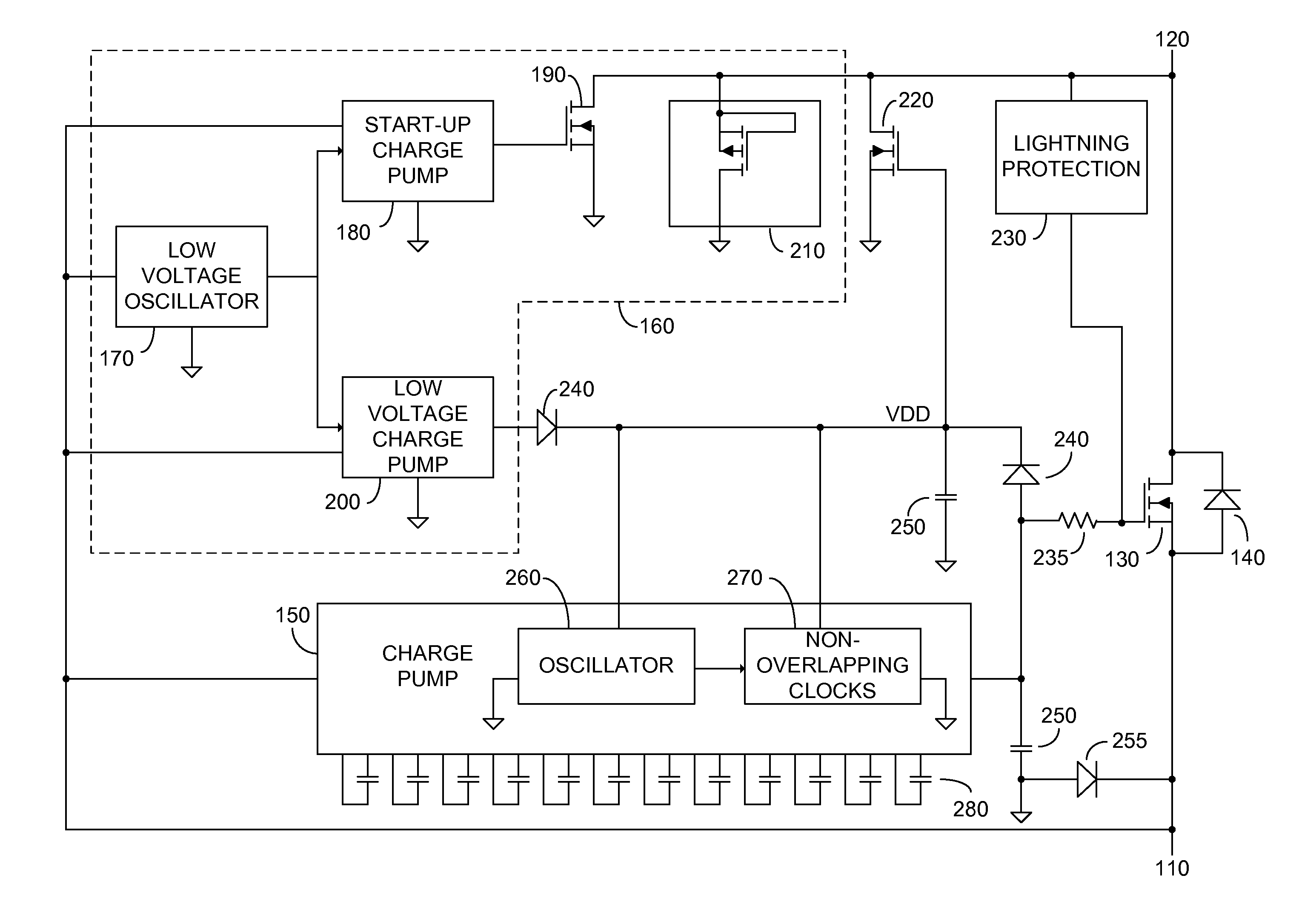
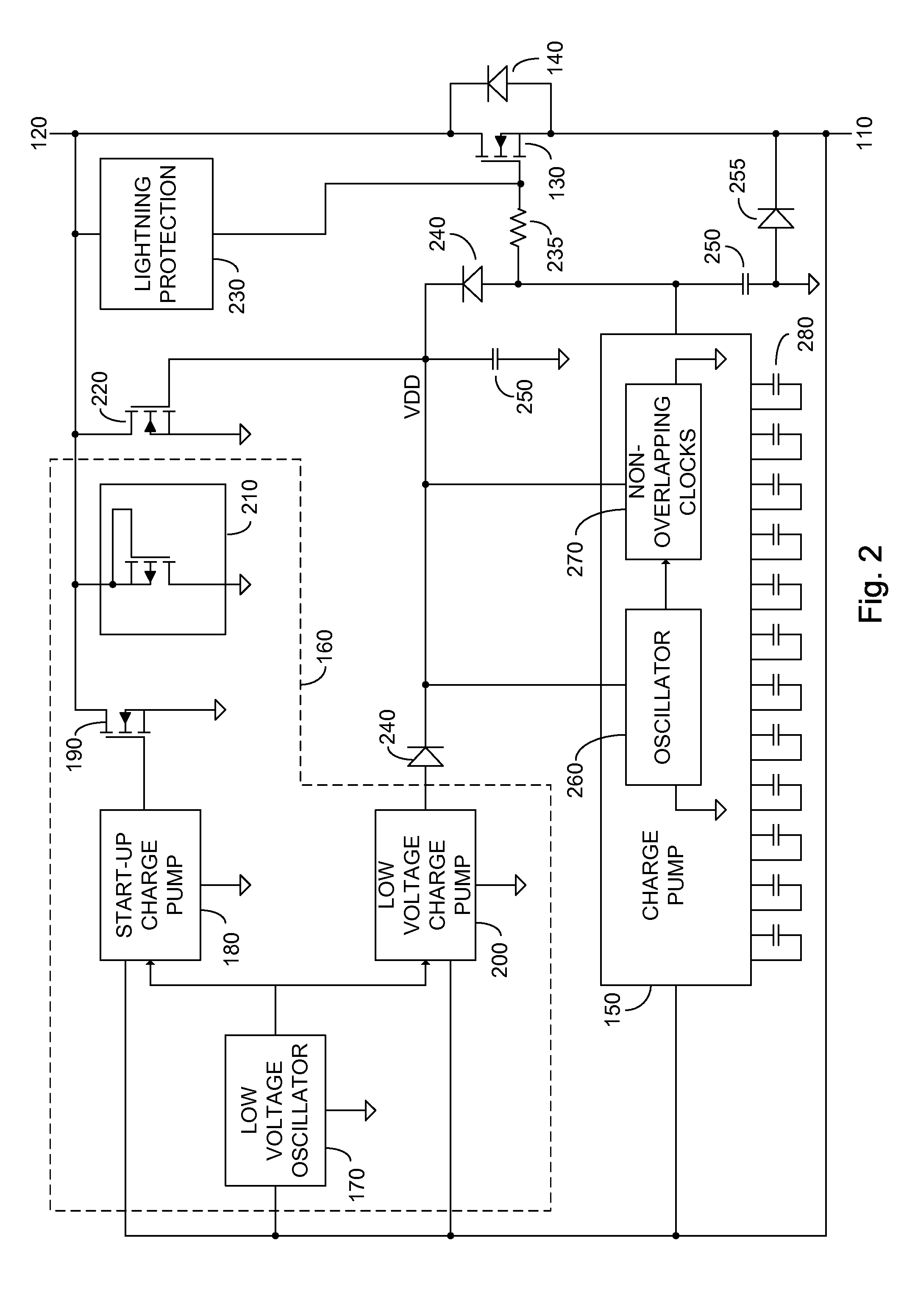
[0025]FIG. 2 illustrates a high level schematic diagram of an exemplary embodiment of a low voltage drop closed loop unidirectional electronic valve comprising: a first terminal 110; a second terminal 120; an electronically controlled switch 130, illustrated without limitation as an NMOSFET; a bypass element 140, illustrated without limitation as the inherent body diode of the NMOSFET of electronically controlled switch 130; a charge pump 150;...


PUM


Abstract

A low voltage drop unidirectional electronic valve constituted of: a first terminal; a second terminal; a first electronically controlled switch coupled between the first terminal and the second terminal; and a first charge pump arranged to close the first electronically controlled switch when the voltage potential at the first terminal is greater than the voltage potential at the second terminal by a first value. The first charge pump is arranged in a closed loop with the first electronically controlled switch so as to continuously maintain the voltage potential at the first terminal greater than the voltage potential at the second terminal by the first value.

Description

CROSS-REFERENCE TO RELATED APPLICATIONS[0001]This application claims priority from U.S. Provisional Patent Application Ser. No. 61 / 224,238 filed Jul. 9, 2009 entitled “Low Voltage Drop Closed Loop Unidirectional Electronic Valve”, the entire contents of which is incorporated herein by reference.BACKGROUND[0002]The invention relates generally to the field of unidirectional electronic valves, and more particularly to a low voltage drop unidirectional electronic valve operating as a near ideal diode.[0003]Solar power for large scale use, and / or for feeding into a power grid, is typically supplied by an array of serially connected solar panels. Each solar panel exhibits a positive terminal, and a return, or negative terminal. Solar panels generate electricity in the presence of an appropriate amount of sunlight, and thus one solar panel in the array may be in a dark condition, while others may be generating electricity. The dark condition may be caused by, among others, a flying object ...

Claims


Application Information

Patent Timeline
Patent Type & Authority Patents(United States)
IPC IPC(8): H03K17/687H01L31/042
CPCH01L31/02021H03K17/063Y02E10/50H02J7/35
Inventor FAHRENBRUCH, SHAWN ANTHONYLIU, GEORGE
Owner MICROSEMI CORP
Why Eureka
Try Eureka