Electronic module and method for producing such a module

a technology of electronic modules and modules, applied in the direction of printed circuit aspects, electrical apparatus construction details, printed circuit non-printed electric components association, etc., can solve the problems of insufficient reliability of contact between semiconductor components of two substrates, two substrates that can be aligned parallel only at very great effort and expense, etc., to achieve the effect of reducing noise, facilitating production and producing qui

Inactive Publication Date: 2012-05-01
ROBERT BOSCH GMBH
View PDF26 Cites 20 Cited by
  • Summary
  • Abstract
  • Description
  • Claims
  • Application Information

AI Technical Summary

Benefits of technology

[0003]The device according to the invention and the production method according to the invention having the characteristics of the independent claims have the advantage that because of the embodiment of the second substrate with a small base, the power components can be secured to the first substrate next to the second substrate. As a result, the second substrate can be located directly on the first substrate, without there being components of different heights located between the two substrates. As a result, the total structural height of the electronic module can be reduced, and an exactly parallel alignment of the two substrates can be attained. The power components can be soldered directly to the first substrate in the horizontal direction next to the second substrate.

Problems solved by technology

The disadvantage of this kind of sandwich construction is that if only one power component is used, or a plurality of power components that have different heights, the two substrates can be aligned parallel to one another only at very great effort and expense, and the contacting between the semiconductor components of the two substrates is not very reliable.

Method used


Image

  • Electronic module and method for producing such a module
  • Electronic module and method for producing such a module

Examples


Embodiment Construction

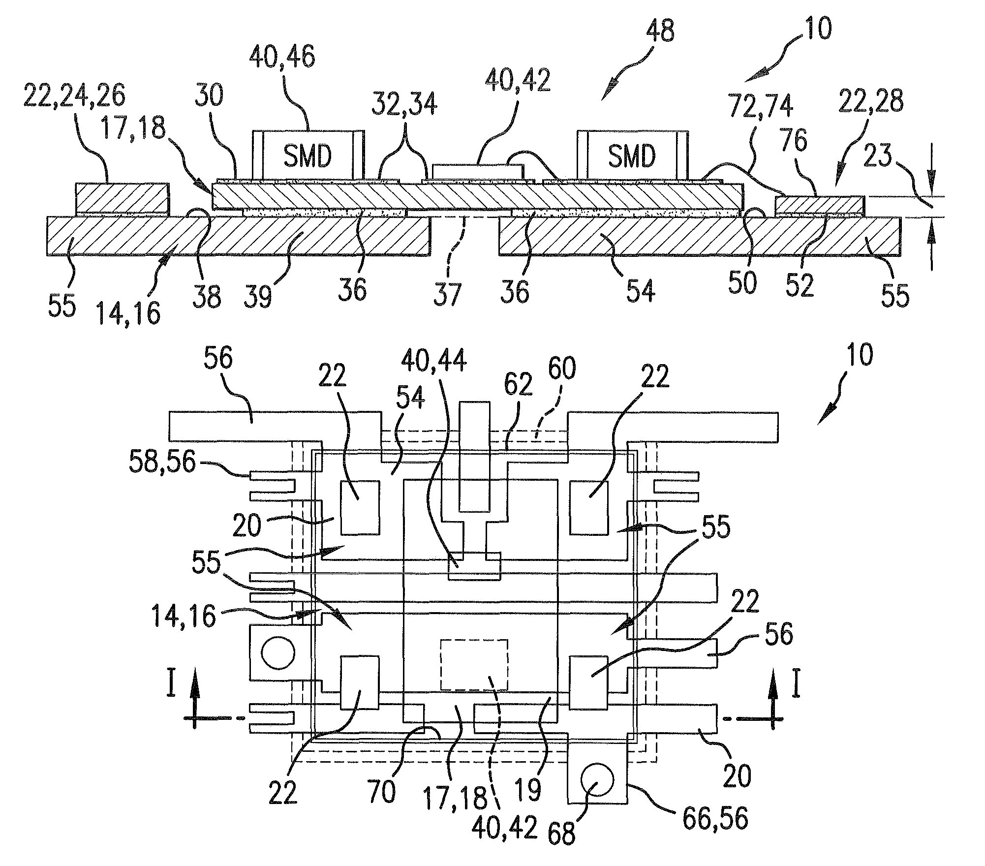
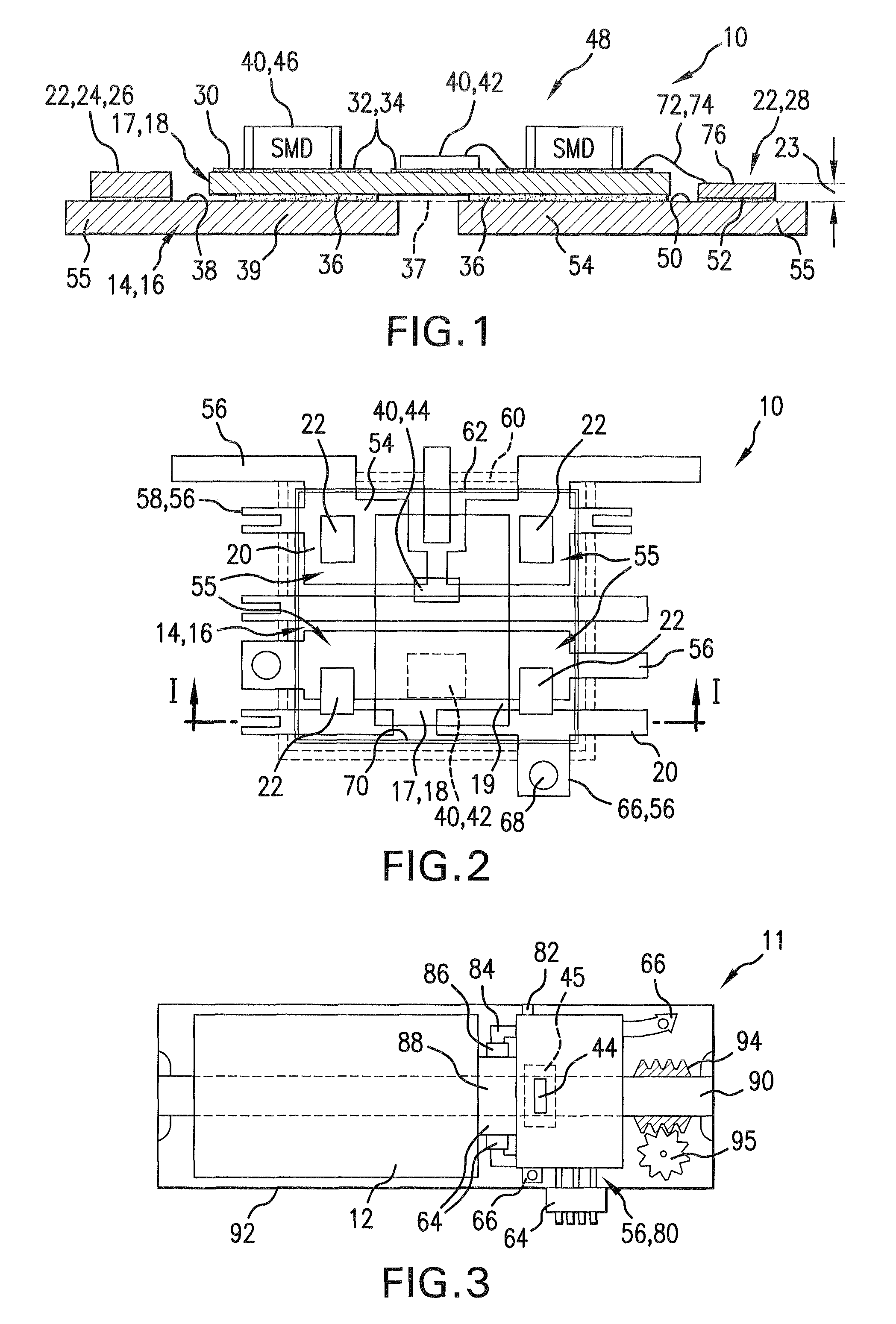
[0020]In FIG. 1, the schematic layout of an electronic unit 10, embodied as an electronic module 10, is shown in section along the line I-I of FIG. 2. As a first, lower substrate 16, a stamped grid 14 is shaped, for instance from a sheet of copper, by means of stamping, bending and embossing with various segments 20. As power components 22, there are diodes 24 or transistors 26, such as power MOSFETs 28, on the stamped grid 14. The power components 22 have different structural heights 23. A ceramic substrate 30 with a metal coating 32, which is embodied in the form of conductor tracks 34, is provided as a second, upper substrate 18. Electronic components 40, such as a microprocessor 42, a position sensor 44, and SMD components 46, which together form the logic element 48 for triggering an electric motor 12, are located on this coating 32 of the second substrate 18 that faces away from the stamped grid 14. The electronic components 40 have been applied to the second substrate 18 by m...


PUM


Abstract

Electronic module (10), and an electric motor (12) containing one, and also a production method for one, having an electrically conductive first substrate (16) which has a basic body (54) and which has a second electrically conductive substrate (18) mounted on it, and having at least one power component which is arranged on a first substrate (16), and the second substrate (18) is fitted with further components (40) on a side (32) which is remote from the first substrate (16), where the second substrate (18) has a smaller base area (19) than the basic body (54) of the first substrate (16), and the power components (22) are mounted on the first substrate (16) outside the outer perimeter (70) of the second substrate (18)—next to the latter.

Description

[0001]The invention relates to an electronic module, to an electric motor containing such a module, and to a method for producing such an electronic module, as generically defined by the preambles to the independent claims.PRIOR ART[0002]In German Patent Disclosure DE 103 52 079 A1, an electric motor has been disclosed which has an electronic module that is located inside the gearbox. The electronic module is embodied here by sandwich construction, in which electronic power components are located between a stamped grid, as a first conductive substrate, and a second conductive substrate. The power components are connected via their upper and lower surfaces directly to the two conductive substrates; the first substrate is connected to the second substrate by means of soldering or a conductive adhesive. The disadvantage of this kind of sandwich construction is that if only one power component is used, or a plurality of power components that have different heights, the two substrates ca...

Claims


Application Information

Patent Timeline
Patent Type & Authority Patents(United States)
IPC IPC(8): H05K7/00H05K1/18
CPCH01L25/162H05K1/021H01L23/49531H01L23/49833H01L23/49861H01L2224/48091H01L2224/48227H01L2924/19105H01L2924/3025H05K1/0306H05K1/182H05K3/0061H05K2201/10446H05K2203/049H01L2924/00014H01L2924/13091H01L2924/13055H01L2924/00
Inventor WOLF, KUNOKOESTER, THOMASHORNUNG, STEFANFEILER, WOLFGANG
Owner ROBERT BOSCH GMBH
Why Eureka
Try Eureka