Aircraft fuel pipe coupling

a technology of fuel pipe coupling and fuel pipe, which is applied in the direction of couplings, pipe supports, pipe elements, etc., can solve the problems of increasing seal and coupling wear, limiting the angular deflection allowable, and using flexible couplings

Active Publication Date: 2012-05-08
AIRBUS OPERATIONS LTD
View PDF20 Cites 17 Cited by
  • Summary
  • Abstract
  • Description
  • Claims
  • Application Information

AI Technical Summary

Benefits of technology

[0019]The double-walled socket arrangement may be defined by a first unitary part. The pipe end fitting may be defined by a second unitary part. The coupling may thereby have fewer parts in comparison to prior art couplings. In certain examples of the present invention, the double-walled socket arrang...

Problems solved by technology

Further complications arise from the need to use flexible couplings in order to compensate for manufacturing tolerances, structural deflections or thermal effects.
This can subject the coupling to side loads that increase seal and coupling wear and can limit the angular deflection allowable between the opposite ends of the coupling, which may for example rotate rel...

Method used


Image

  • Aircraft fuel pipe coupling
  • Aircraft fuel pipe coupling
  • Aircraft fuel pipe coupling

Examples


first embodiment

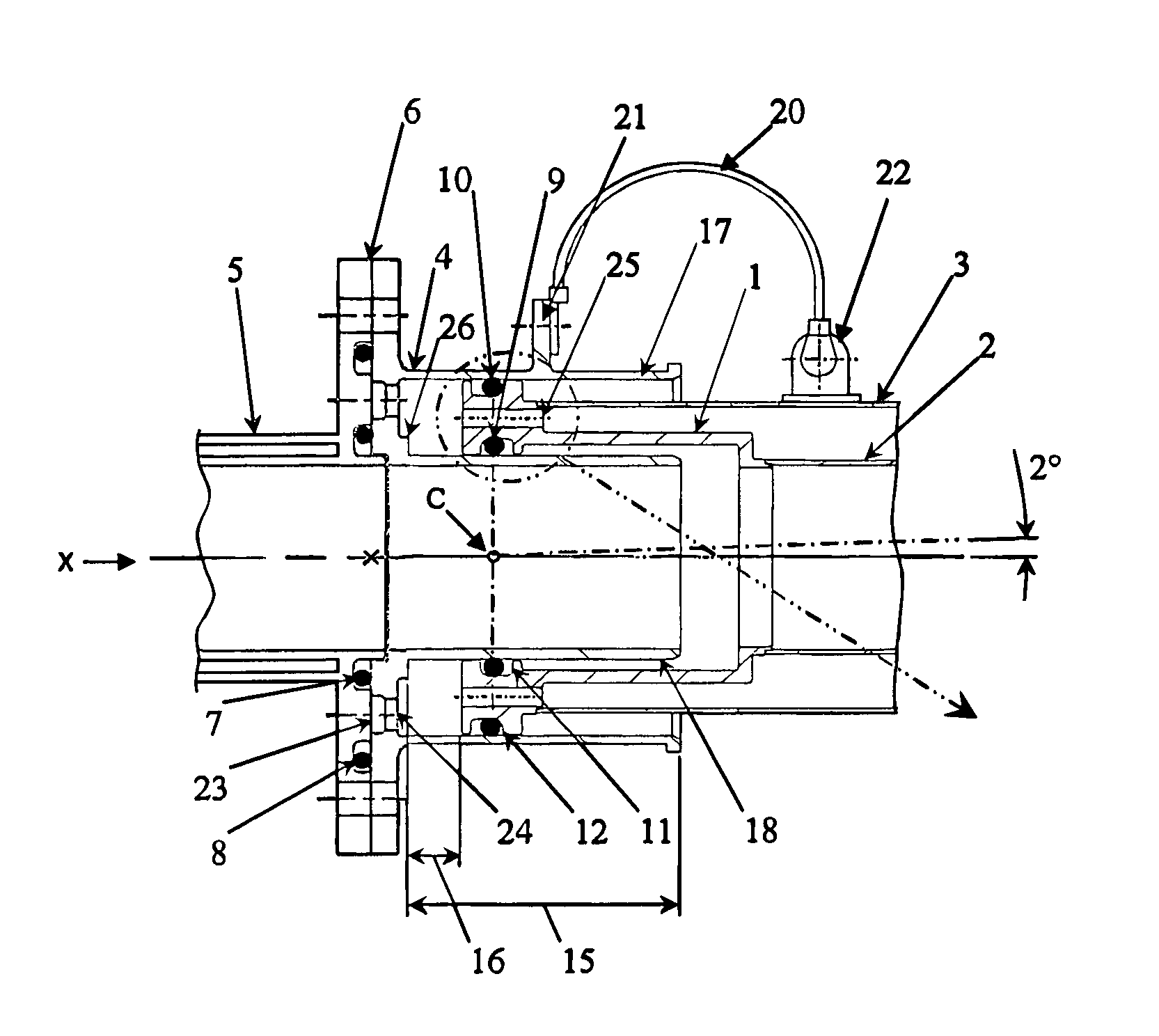
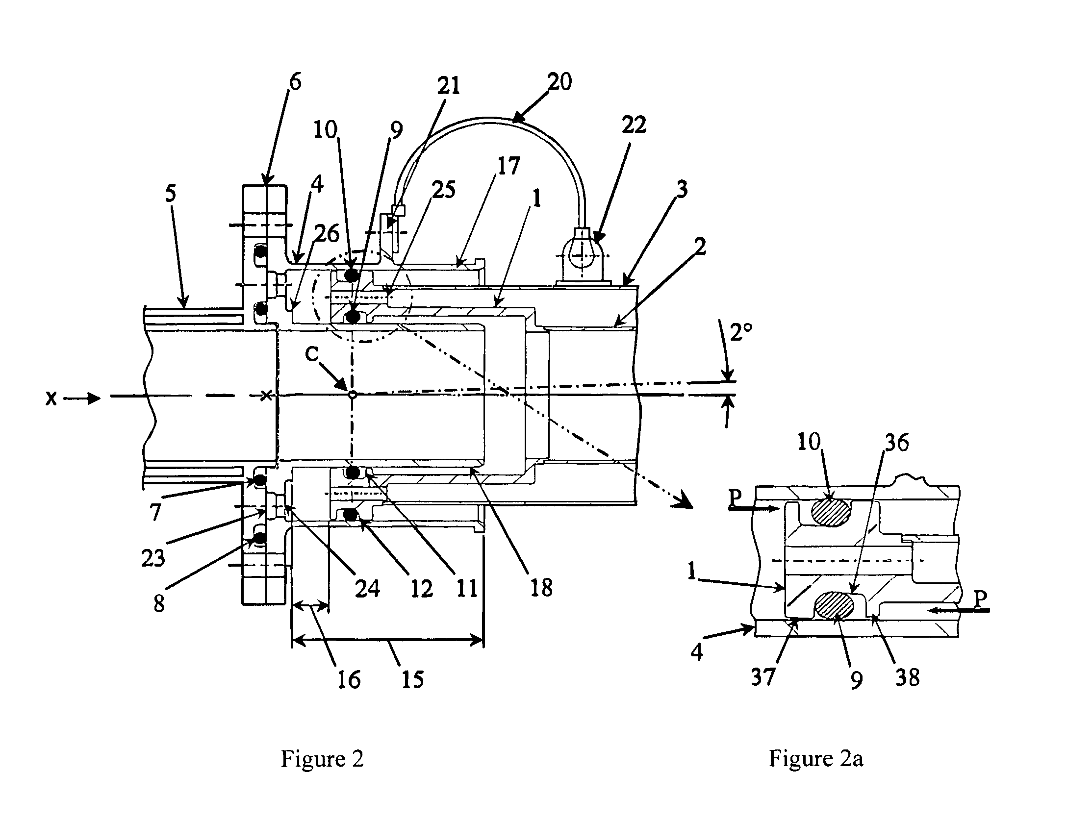
[0042]FIGS. 2 and 2a show a coupling according to the invention. The coupling is arranged about an axis X and joins a double-walled rigid pipe 5 (on the left in FIG. 2) and a double-walled rigid pipe (on the right in FIG. 2) comprising an inner rigid pipe wall 2 and an outer rigid pipe wall 3. The coupling comprises a unitary end fitting 1 attached by fusion welding to the double-walled pipe 2, 3. The coupling also comprises a unitary double-walled socket 4 attached to the adjacent double-walled pipe 5 by means of a split flange, the split flange comprising a flange on the pipe 5 and a corresponding flange on the double-walled socket 4, the split line indicated by the arrow 6. The pipe 5 in this embodiment is in the form of a double-walled connector pipe including an end flange, which is rigidly attached to the aircraft structure (to the rear spar - not shown). The connection of the double-walled socket 4 and the single-walled pipe 5 is sealed by an inner static 0-ring seal 7 and an...

fourth embodiment

[0054]FIG. 7 shows a fourth embodiment whereby the double pipe end fitting 1 is retained in the double-walled socket 4 by means of a threaded retaining nut 31 and a split ring 32 fastened to the outer socket 17, which incorporates an external thread 33. The provision of the split ring 32 provides a means for varying the angular deflection allowed between the end fitting 1 and the double-walled socket 4. The dimensions of the split ring 32 may be chosen in accordance with the required angular flexibility of the relative pivoting between the end fitting 1 and the double-walled socket 4. The nut may provide additional fire risk protection.

fifth embodiment

[0055]FIG. 8 shows a fifth embodiment suitable for application within a continuous double-walled pipe installation, two double sockets 4a, 4b are integrated into a single-piece connector 34 which is rigidly attached to the aircraft structure (not shown) by means of an integral flange 35 with bolt holes therein. Each socket 4a, 4b receives a pipe end fitting la, lb attached to the end of a double-walled pipe assembly. The fuel pipe installation may then comprise successive double-walled pipes, each having end fittings mounted at either end, joined by double-walled couplings 34. Such an installation would provide leak containment for inner pipes 2a, 2b and inner couplings 17.

[0056]FIG. 9 shows an sixth embodiment for an application within a single-walled pipe installation. In this embodiment, in contrast to the first embodiment, only a single walled pipe 2 is connected to the end fitting 1. Therefore, the outer pipe and drain holes in the double pipe end fitting need not be present. T...


PUM


Abstract

A coupling for fuel pipe includes a pipe end fitting, which includes a male outer surface including a groove and a female inner surface including a groove. The coupling includes a double-walled socket including a female outer socket and a male inner shaft. The pipe end fitting is accommodated in the region between the female outer socket and the male inner shaft. A first seal ring seals between the female inner surface and the male inner shaft. A second seal ring, which may be substantially coplanar with the first, seals between the male outer surface and the female outer socket of the double-walled socket. The coupling may be so arranged that the pipe end fitting and the double-walled socket are able to pivot relative to each other by up to at least ±2 degrees and are able to slide both towards and apart from each other.

Description

[0001]This application is the U.S. national phase of International Application No. PCT / GB2006 / 003744, filed 6 Oct. 2006, which designated the U.S. and claims priority to Great Britain Application No. 0523573.4, filed 18 Nov. 2005, the entire contents of each of which are hereby incorporated by reference.BACKGROUND OF THE INVENTION[0002]1. Field of the Invention[0003]The present invention relates to aircraft fuel pipe couplings and in particular but not exclusively flexible pipe couplings for connecting a double-walled pipe in an aircraft fuel system to another fuel pipe.[0004]2. Discussion of Prior Art[0005]In aircraft fuel systems it is often necessary to use double-walled pipes, connectors and couplings in order to protect from fuel leakage. When the risk of leakage is high, for example in the pressurised fuselage of an aircraft, the entire fuel system may be double-walled. Where the risk of leakage is less, it may only be the couplings that are double-walled. Further complication...

Claims


Application Information

Patent Timeline
IPC IPC(8): F16L27/12F16L39/04F16L39/00
CPCF16L39/005F16L39/04F16L25/01F16L2201/30B64D37/14
Inventor PETIT, DAVIDBRYANT, ANTHONY JOHN
Owner AIRBUS OPERATIONS LTD
Why Eureka
Try Eureka