
Carriageless mobilized storage unit for use in a mobile storage system

a storage unit and mobile technology, applied in the direction of loading/unloading, kitchen cabinets, cabinets, etc., can solve the problems of significant shipping costs, time and cost in assembly of separate parts, and the separate construction of the carriage and storage unit involves a large number of parts, so as to achieve convenient transportation and storage, the effect of reducing the number of parts and reducing the cost of transportation

Active Publication Date: 2012-05-08
SPACESAVER
View PDF19 Cites 5 Cited by
  • Summary
  • Abstract
  • Description
  • Claims
  • Application Information

AI Technical Summary

Benefits of technology

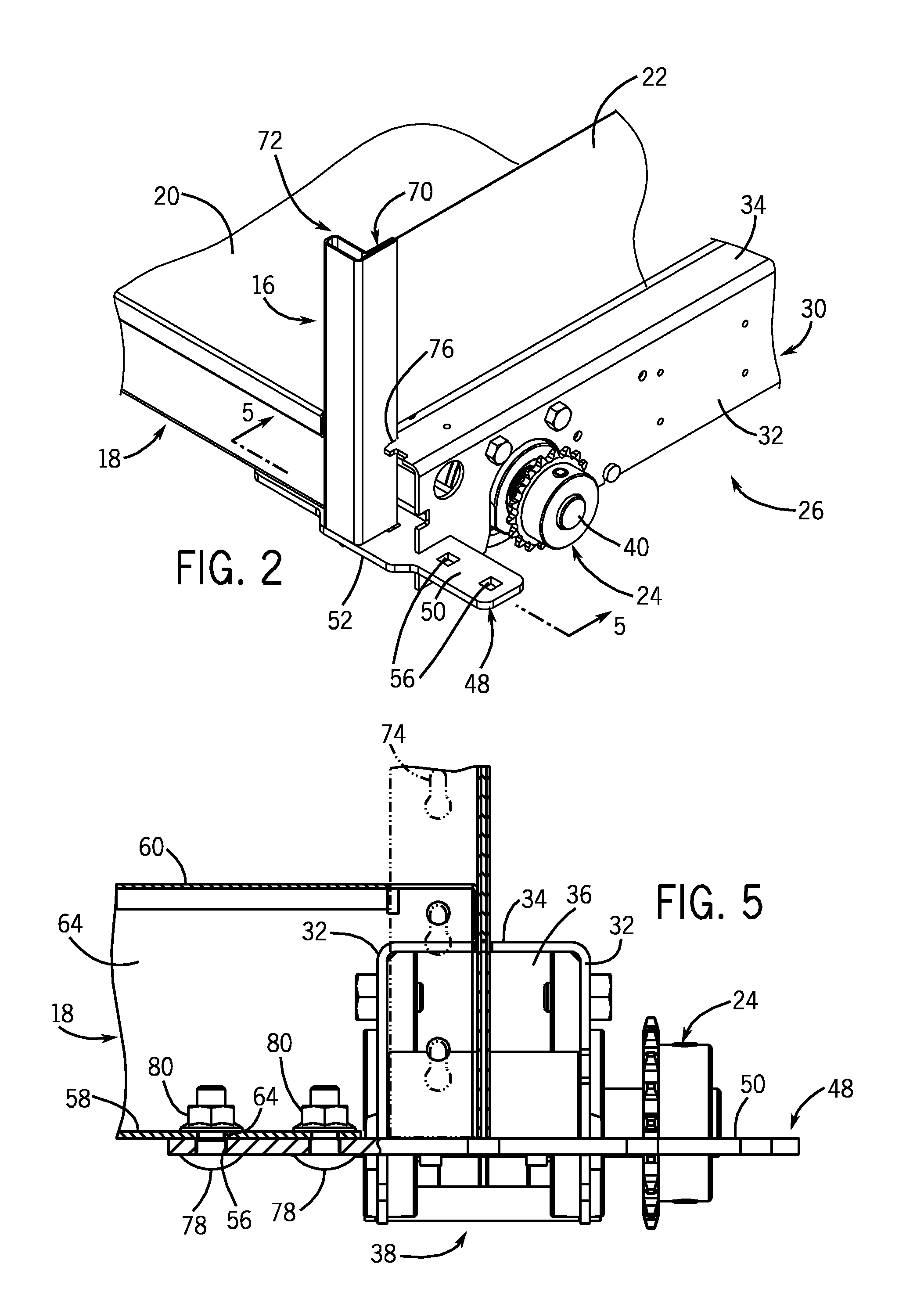
"The present invention is about a new mobile storage system that solves the problems of a separate carriage and storage units by integrating the carriages and storage units into one structure. This system is simple in its components, can be manufactured and shipped to an installation site in a knock-down manner, and provides adequate strength and rigidity for use in a normal mobile storage application. The mobile storage unit includes a pair of axially extending wheel units, each with a wheel arrangement, and a storage unit support structure consisting of upright and transverse support members that extend between the wheel units. The support members are secured to the wheel units and the end areas of the wheel units, and the lowermost shelf support member is secured to an upwardly facing engagement surface on the end area of one of the wheel units. The invention also includes a method of mobilizing the mobile storage unit and a mobile storage unit for use in a mobile storage system."

Problems solved by technology

While this construction of a mobile storage system is reliable and proven, there are certain disadvantages in that the separate construction of the carriage and the storage units involves a significant number of parts as well as time and cost in assembly of the separate parts.
This can result in significant shipping costs.

Method used


Image

  • Carriageless mobilized storage unit for use in a mobile storage system
  • Carriageless mobilized storage unit for use in a mobile storage system
  • Carriageless mobilized storage unit for use in a mobile storage system

Examples


Embodiment Construction

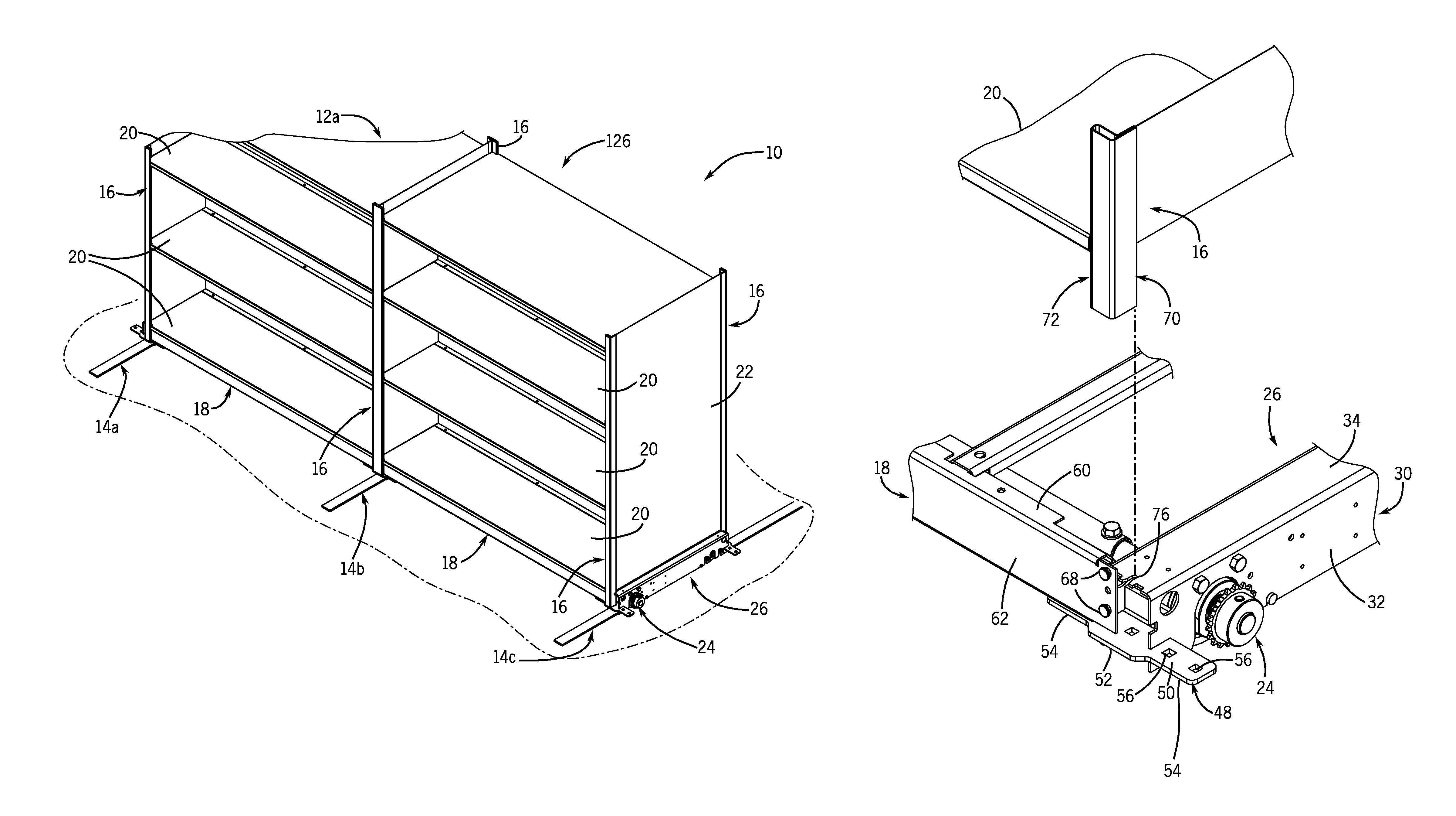
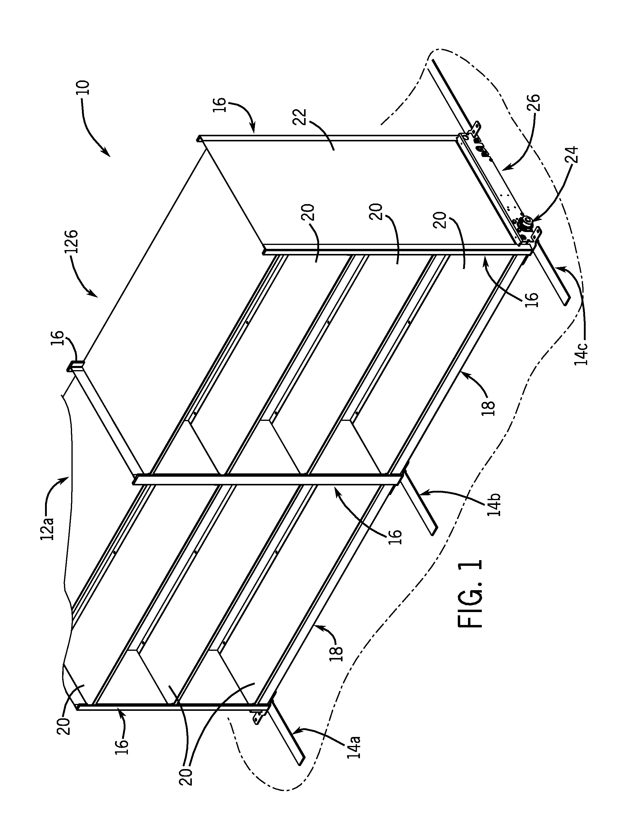
[0016]Referring to FIG. 1, a mobile storage system 10 generally includes a series of storage units, such as shown at 12a, 12b, which are connected together and are movable on a series of rails, such as shown at 14a, 14b and 14c. Generally, the storage units 12a and 12b are made up of a series of upright support members 16, the end ones of which are generally L-shaped and the intermediate ones of which are generally T-shaped. A series of shelf support members 18 extend between and interconnect the upright support members 16, and are operable to support a series of shelves 20. It is understood that, while FIG. 1 illustrates two storage units, storage system 10 may be made up of any number of storage units.

[0017]Storage units 12a and 12b are movable on rails 14a-14c by operation of a drive system that is generally constructed in a manner as known in the art. The drive system includes a manually operated crank that is secured to one of the end panels of the storage system 10, such as sh...


PUM


Abstract

A mobile storage unit for a mobile storage system includes a pair of axially extending wheel units, each of which defines spaced apart end areas and includes a wheel arrangement. A storage unit support structure is interconnected with the wheel units, and includes upright support members and shelf support members. A pair of upright support members are engaged with and supported by the end areas of each wheel unit. A lowermost shelf support member is secured to an end area of one of the wheel units. The lowermost shelf support members are secured to the upright support members and to the end areas of the wheel units. Each end area of each wheel unit includes an upwardly facing engagement surface, and the lowermost shelf support member is secured to the upwardly facing engagement surface. The upright support members are also supported by the upwardly facing engagement surface.

Description

BACKGROUND AND SUMMARY OF THE INVENTION[0001]The present invention relates generally to mobile storage systems and, more particularly, to a low profile wheel support assembly for use with a mobile storage unit.[0002]Mobile storage systems have long been utilized to store documents, books and other items in a high density manner that also allows for easy access to the items contained on any portion of the mobile storage system. These systems typically include a number of storage units movably mounted on rails that are secured to the floor of a room or other enclosure. By operation of a motive system associated with each of the storage units, individual units may be moved along the rails to expose a desired unit in order to retrieve the items contained therein.[0003]Typically, the mobile storage system consists of a number of carriages that are movable on the rails, in combination with storage units that are mounted to the carriages. The carriages and storage units are separate struct...

Claims


Application Information

Patent Timeline
Patent Type & Authority Patents(United States)
IPC IPC(8): A47B53/00A47B87/00A47B77/00A47B95/00A47B88/493
CPCA47B53/02
Inventor MUTH, JAMES C.
Owner SPACESAVER
Learn More