Wind turbine blade and wind turbine generator using the same

a technology of wind turbine generator and wind turbine blade, which is applied in the manufacture of final products, vessel construction, marine propulsion, etc., can solve the problems of not using reference numbers and codes used here to understand the scope of claims, and the time for manufacturing is long, so as to prevent the increase of the weight of the blade, shorten the manufacturing time and manufacturing ease, and reduce the cost

Active Publication Date: 2012-05-08
MITSUBISHI HEAVY IND LTD
View PDF12 Cites 18 Cited by
  • Summary
  • Abstract
  • Description
  • Claims
  • Application Information

AI Technical Summary

Benefits of technology

[0031]According to the present invention, it is possible to provide a wind turbine blade and a wind turbine generator using the wind turbine blade that achieve a shorter manufacturing time and ease of the manufacturing. It is also possible to provide a wind turbine blade and a wind turbine generator using the wind turbine blade that achieve a shorter manufacturing time and ease of the manufacturing while preventing the weight increase of the blade.

Problems solved by technology

There are many places where the UD material 112 needs to be laminated, which takes time and thus, the time for manufacturing is long.
As a result, the UD material tends to droop down and it becomes difficult to manufacture the blade.
However, the reference numbers and codes used here should not be used to understand the scope of the claims.

Method used


Image

  • Wind turbine blade and wind turbine generator using the same
  • Wind turbine blade and wind turbine generator using the same
  • Wind turbine blade and wind turbine generator using the same

Examples


first preferred embodiment

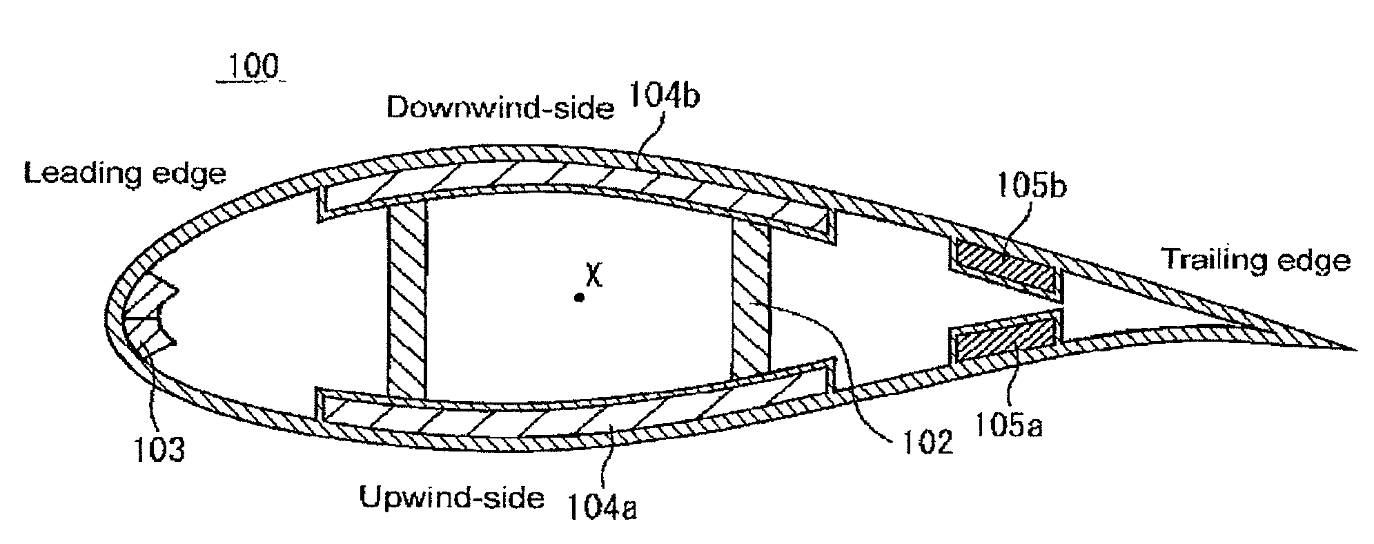
[0044]A wind turbine blade in relation to a first preferred embodiment of the present invention is described in reference to the attached drawings. FIG. 4A is a schematic view showing a structure of the wind turbine blade in relation to the first preferred embodiment of the present invention. This wind turbine blade 10 has an outer shell 1 of a basic laminated structure, an upwind-side reinforcing section 4a and a downwind-side reinforcing section 4b. The upwind-side reinforcing section 4a and the downwind-side reinforcing section 4b have a reinforced laminated structure. The upwind-side reinforcing section 4a and the downwind-side reinforcing section 4b are provided in an upwind-side part and a downwind-side part of the wind turbine blade 10 respectively.

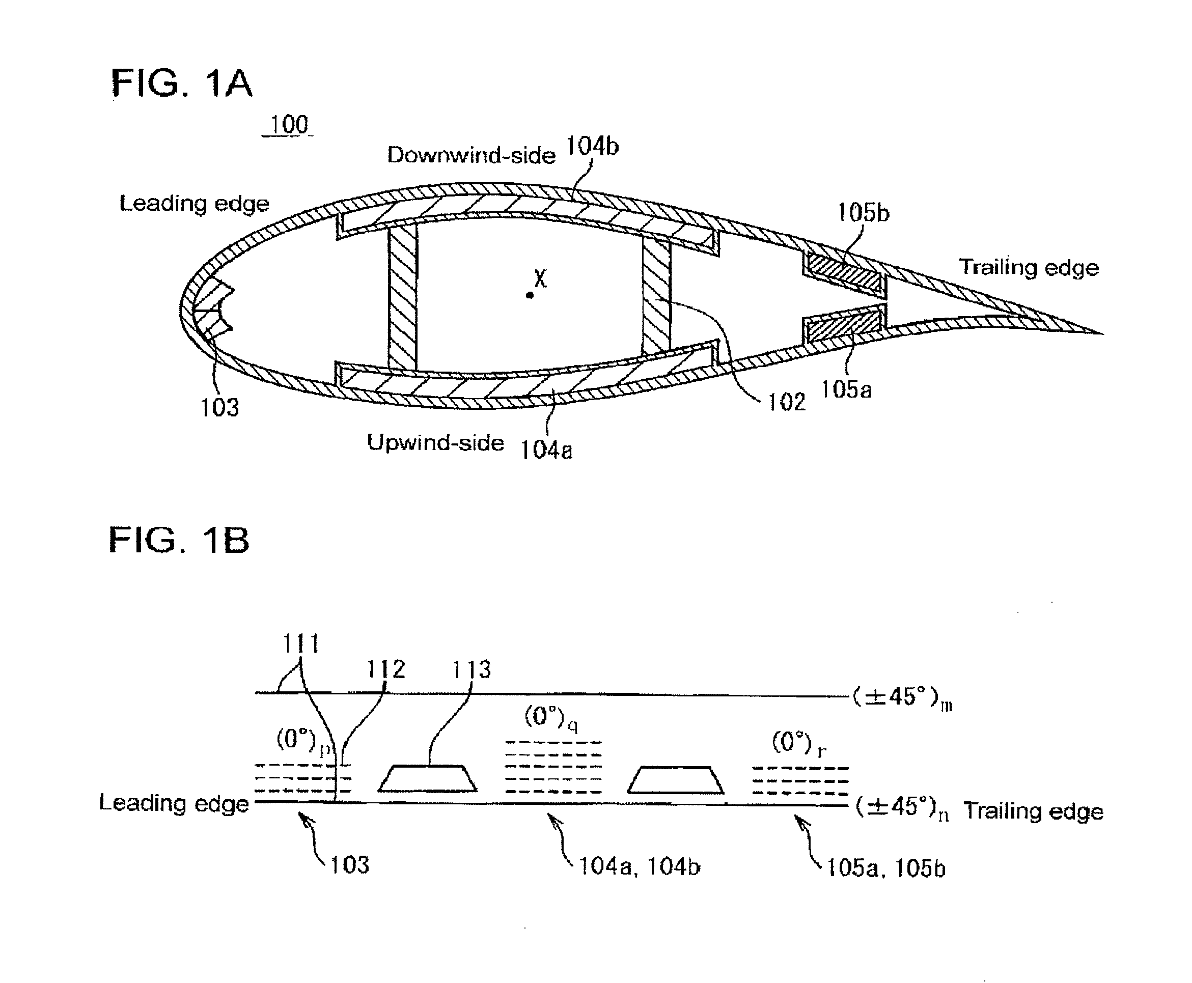
[0045]A structure having a fiber-reinforced plastic of unidirectional reinforcing material 12 (UD material or 0° material) arranged in a location far from a flexural center X is popular to make a lighter blade 10 while maintaining ...

second preferred embodiment

[0055]A wind turbine blade in relation to a second preferred embodiment of the present invention is described in reference to the attached drawings. FIG. 5A is a sectional view schematically showing a structure of a wind turbine blade in relation to the second preferred embodiment of the present invention. The wind turbine blade 10a has an outer shell 1 of a basic laminated structure, an upwind-side reinforcing section 4a, a downwind-side reinforcing section 4b, and trailing edge reinforcing sections 5a, 5b. The upwind-side reinforcing section 4a, the downwind-side reinforcing section 4b and the trailing edge reinforcing sections 5a, 5b have a reinforced laminated structure. The upwind-side reinforcing section 4a, the downwind-side reinforcing section 4b and the trailing edge reinforcing sections 5a, 5b are provided in the upwind-side part, the downwind-side and the leading edge part of the wind turbine blade 10 respectively.

[0056]The second preferred embodiment is different from th...

third preferred embodiment

[0067]A wind turbine blade in relation to a third preferred embodiment of the present invention is described in reference to the attached drawings. FIG. 6 is a sectional view schematically showing a structure of a wind turbine blade in relation to the third preferred embodiment of the present invention. This wind turbine blade 10b has a blade root section S1 and a main section S2.

[0068]In the preferred embodiment, instead of applying the same laminated structure to the entire wind turbine blade, the blade root section S1 from the root to vicinity of a maximum chord location of the blade, and the main section S2 from the maximum chord location to a tip of the blade have different laminated structures. This is different from the first and second preferred embodiments. The above structure is described in detailed below.

[0069]The blade root section S1 is near the blade root and has an almost cylindrical shape, which causes the UD material to droop down. Thus, the laminated structure of ...


PUM


Abstract

A wind turbine blade includes a laminated structure having an outer shell (1) having a shape of the blade, an upwind-side reinforcing section (4a) which reinforces a upwind-side part of the blade in the outer shell 1 and a downwind-side reinforcing section 4b which reinforces a downwind-side part of the blade in the outer shell 1. The outer shell 1 includes a first multidirectional material, a first unidirectional reinforcing material 12 and another multidirectional material 11 which are layered. The upwind-side reinforcing section 4a includes another unidirectional reinforcing material 12 provided between the first unidirectional reinforcing material 12 and another multidirectional material 11. The downwind-side reinforcing section 4b includes yet another unidirectional reinforcing material provided between the unidirectional reinforcing material 12 and the multidirectional material 11. The outer shell 1 includes a first core member 13 respectively provided between the upwind-side reinforcing section 4a and the downwind-side reinforcing section 4b on a leading edge side, and between the upwind-side reinforcing section 4a and the downwind-side reinforcing section 4b on a trailing edge side.

Description

RELATED APPLICATIONS[0001]The present application is continuation from National Phase of International Application No. PCT / JP2010 / 070797 filed Nov. 22, 2010, and claims priority from Japanese Application No. 2009-290660, filed Dec. 22, 2009, the disclosure of which is hereby incorporated by reference herein in its entirety.BACKGROUND OF THE INVENTION[0002]1. Field of the Invention[0003]The present invention relates to a wind turbine blade and a wind turbine generator using the wind turbine blade.[0004]2. Description of the Related Art[0005]The wind turbine blade for a wind turbine generator is desired to be lightweight, highly reliable and easy to manufacture for saving production time thereof. In view of making the wind turbine blade lightweight, the wind turbine blade is configured to have a laminated structure of composite materials. FIG. 1A is a sectional view schematically illustrating a structure of a wind turbine blade. The blade 100 comprises an outer shell 101 having a basi...

Claims


Application Information

Patent Timeline
Patent Type & Authority Patents(United States)
IPC IPC(8): F01D5/14
CPCF03D1/0675F03D1/0683Y02E10/722Y02E10/721F05B2280/6003Y02E10/72Y02P70/50F05B2240/221
Inventor HIRANO, TOSHIYUKIESAKI, KOUJIKUROIWA, TAKAO
Owner MITSUBISHI HEAVY IND LTD
Why Eureka
Try Eureka