Devices and methods for inter-vertebral orthopedic device placement

a technology of orthopedic devices and implants, applied in the field of devices and methods for implantation of orthopedic devices, can solve the problems of limited mobility, significant proportion of low back pain, clumsiness, etc., and achieve the effect of accurately placing an orthopedic devi

Active Publication Date: 2012-05-08
ABDOU M S
View PDF246 Cites 49 Cited by
  • Summary
  • Abstract
  • Description
  • Claims
  • Application Information

AI Technical Summary

Benefits of technology

[0012]The placement system described herein provides an easy and reliable way of placing an orthopedic device within the inter-spinous ligament. Using this method, the implant can be placed rapidly, precisely, with a few small skin incisions and the absolute minimum amount of tissue dissection. It permits minimally invasive device placement using only local anesthesia into those afflicted patients who are least able to withstand the stress of open surgical intervention.

Problems solved by technology

Eventually, the canal dimensions become sufficiently small so as to significantly compress the nerve elements and produce pain, weakness, sensory changes, clumsiness and other manifestation of nervous system dysfunction.
This condition is very common in the elderly and causes a significant proportion of the low back pain, lower extremity pain, lower extremity weakness, limitation of mobility and the high disability rates that afflict this age group.
Despite advances in surgical technique, spinal decompression surgery can be an extensive operation with risks of complication from the actual surgical procedure and the general anesthetic that is required to perform it.
Since many of these elderly patients are in frail health, the risk of developing significant peri-operative medical problems remains high.
In addition, the traditional treatment of surgical resection of spinal structures may relieve the neural compression but lead to spinal instability in a substantial minority of patients.
That is, removal of the spinal elements that compress the nerves may cause the spinal elements themselves to move in an abnormal fashion relative to one another and produce pain.
Unfortunately, the placement of each device requires exposure of the spinous processes and the posterior aspect of the spinal column.
Thus, these operations still present a significant risk of peri-operative complications in this frail patient population.

Method used


Image

  • Devices and methods for inter-vertebral orthopedic device placement
  • Devices and methods for inter-vertebral orthopedic device placement
  • Devices and methods for inter-vertebral orthopedic device placement

Examples


Embodiment Construction

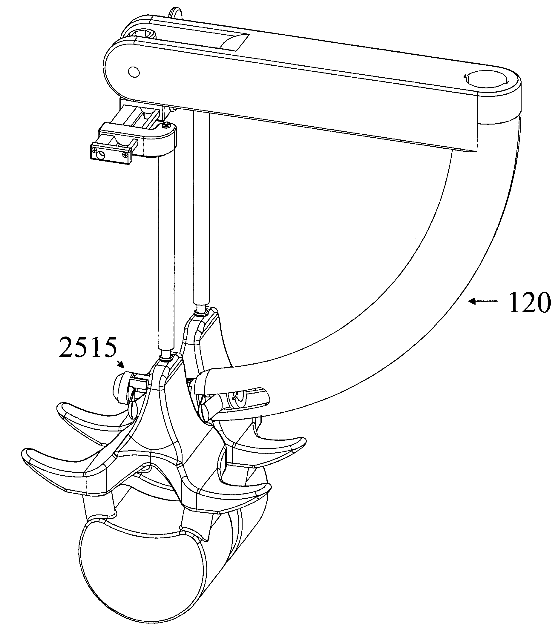
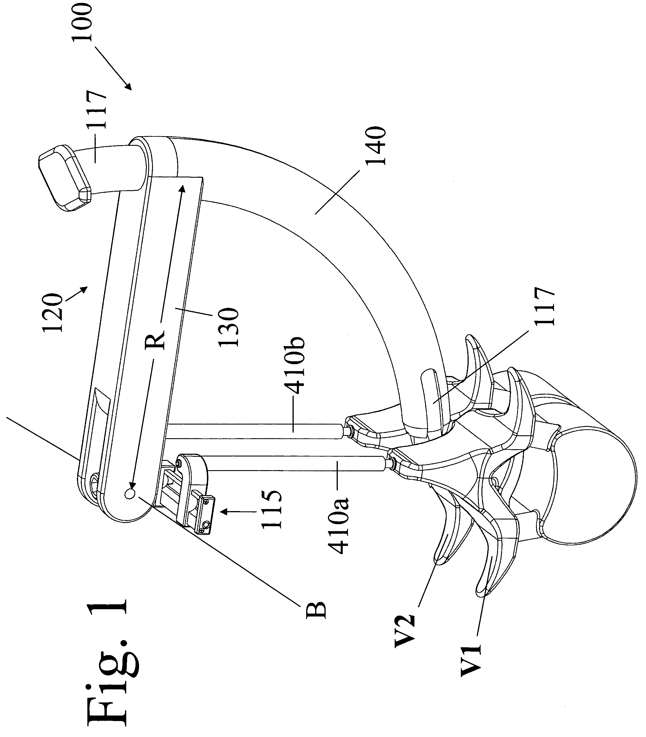
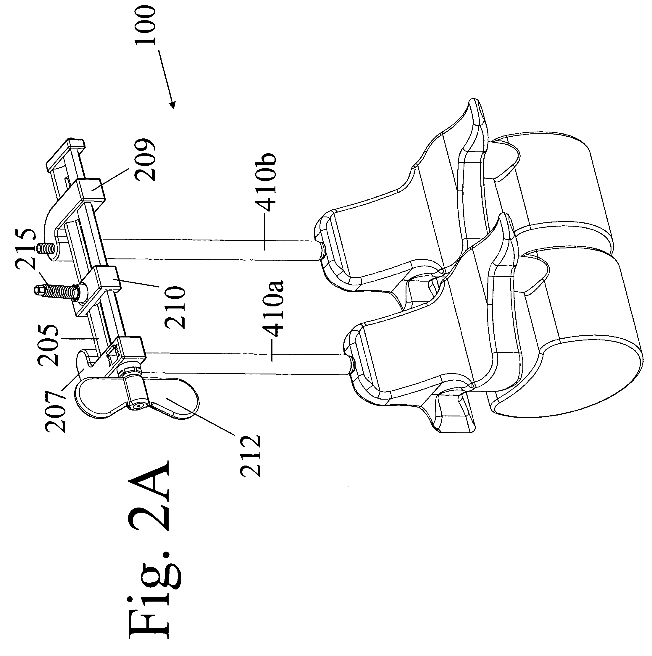
[0073]Disclosed are methods and devices for implanting a device (such as an orthopedic device) between skeletal segments (such as vertebrae), using limited surgical dissection. The implanted devices are used to adjust and maintain the spatial relationship(s) of adjacent bones.

[0074]FIG. 1 shows a perspective, assembled view of a distractor device 100 for implanting an orthopedic device between skeletal segments, such as between a first vertebral body V1 and a second vertebral body V2. For clarity of illustration, the vertebral bodies are represented schematically and those skilled in the art will appreciate that actual vertebral bodies include anatomical details not shown in FIG. 1. Moreover, although described in the context of being used with vertebrae, it should be appreciated the device 100 and associated methods can also be used with other skeletal segments.

[0075]The device 100 generally includes a pair of anchors that include elongate distraction screws 110a and 110b (collecti...


PUM


Abstract

The disclosure relates to devices and methods for implantation of an orthopedic device between skeletal segments using limited surgical dissection. The implanted devices are used to adjust and maintain the spatial relationship(s) of adjacent bones. Depending on the implant design, the motion between the skeletal segments may be increased, limited, modified, or completely immobilized.

Description

REFERENCE TO PRIORITY DOCUMENT[0001]This application claims priority of U.S. Provisional Patent Application Ser. No. 60 / 631,213, filed Nov. 24, 2004 and U.S. Provisional Patent Application Ser. No. 60 / 713,235, filed Aug. 31, 2005. Priority of the aforementioned filing dates is hereby claimed, and the disclosures of the Provisional Patent Applications are hereby incorporated by reference in their entirety.BACKGROUND[0002]The disclosure relates to devices and methods for implantation of an orthopedic device between skeletal segments using limited surgical dissection. The implanted devices are used to adjust and maintain the spatial relationship(s) of adjacent bones. Depending on the implant design, the motion between the skeletal segments may be increased, limited, modified, or completely immobilized.[0003]Progressive constriction of the central canal within the spinal column is a predictable consequence of aging. As the spinal canal narrows, the nerve elements that reside within it b...

Claims


Application Information

Patent Timeline
Patent Type & Authority Patents(United States)
IPC IPC(8): A61B17/70A61B17/58A61B17/60
CPCA61B17/7065A61B17/7077A61F2/4611A61B17/7062A61B2017/0256A61B2019/461A61F2002/4687A61B2019/464A61F2002/4658A61F2002/4662A61F2002/4666A61B2019/462A61B2090/064A61B2090/061A61B2090/062A61F2/4405A61F2/4657A61F2002/4627
Inventor ABDOU, M. S.
Owner ABDOU M S
Why Eureka
Try Eureka