Particle reduction on surfaces of chemical vapor deposition processing apparatus

a chemical vapor deposition and processing apparatus technology, applied in the direction of foil printing, manufacturing tools, plasma technology, etc., can solve the problems of affecting the overall performance of the solar cell, reducing the yield of operable devices produced on a semiconductor substrate, and major defects on the surface of photodiodes used in small device displays and indicators

Inactive Publication Date: 2012-05-08
APPLIED MATERIALS INC
View PDF78 Cites 115 Cited by
  • Summary
  • Abstract
  • Description
  • Claims
  • Application Information

AI Technical Summary

Problems solved by technology

Solar cells are also of particular interest at this time, due to the high cost of traditional energy sources.
Due to the nanometer sized features of today's semiconductor devices, the presence of particulates on device surfaces substantially reduces the yield of operable devices produced on a semiconductor substrate.
The particulate problem is particularly important when the device surface is of the size used in flat panel displays where the inoperability of contaminated devices in the area of the particulates produces a defect which is a readily apparent source of distraction to the user of display device.
Defects on photodiode surfaces used in small device displays and indicators is also a major problem.
While defects on solar cell surfaces may not be as critical, the overall performance of the solar cell may be affected if the contaminant level is sufficiently high.
As the size of flat panel displays increase, it becomes increasingly difficult to control particulate generation during the thin film deposition processes.
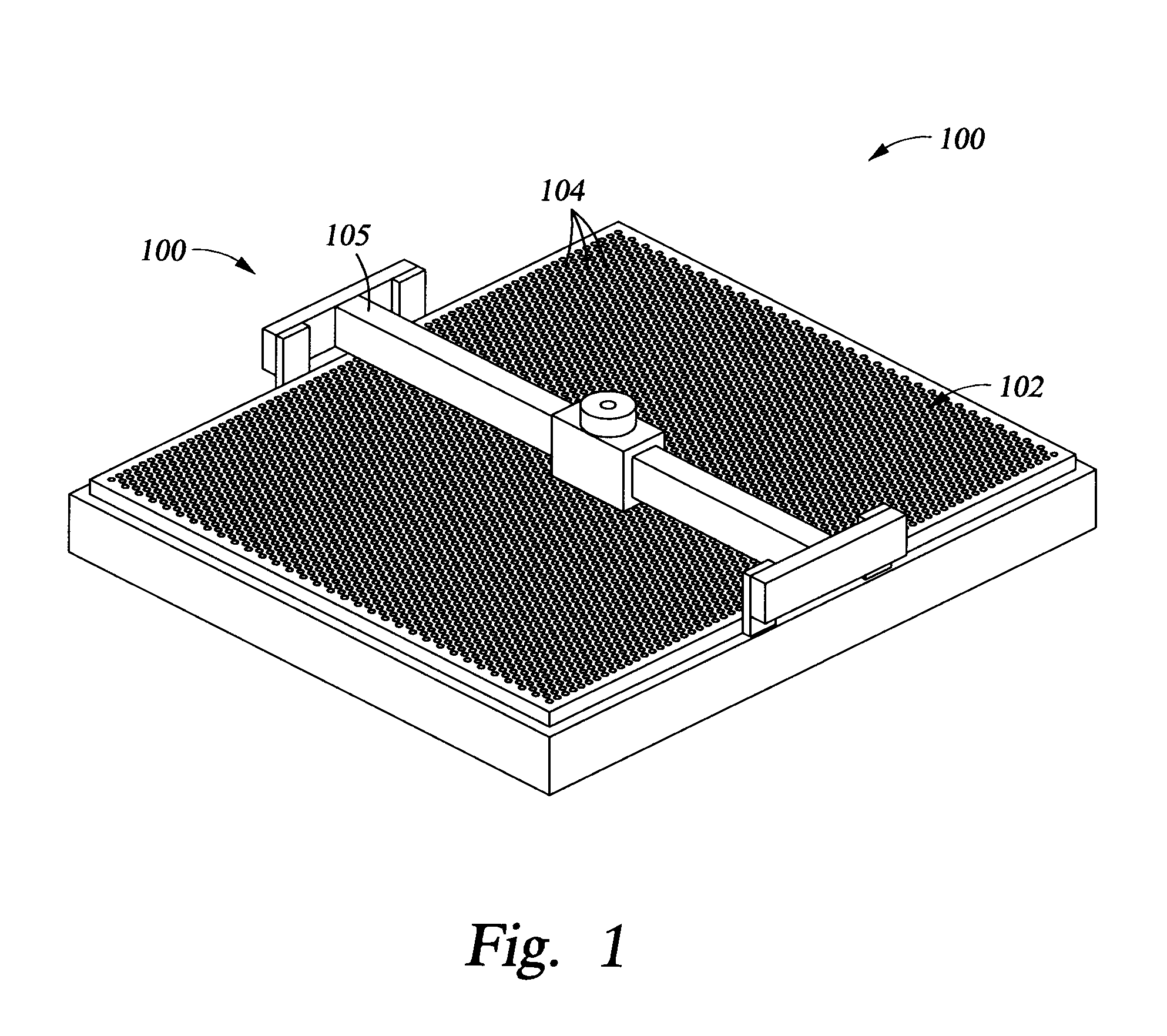
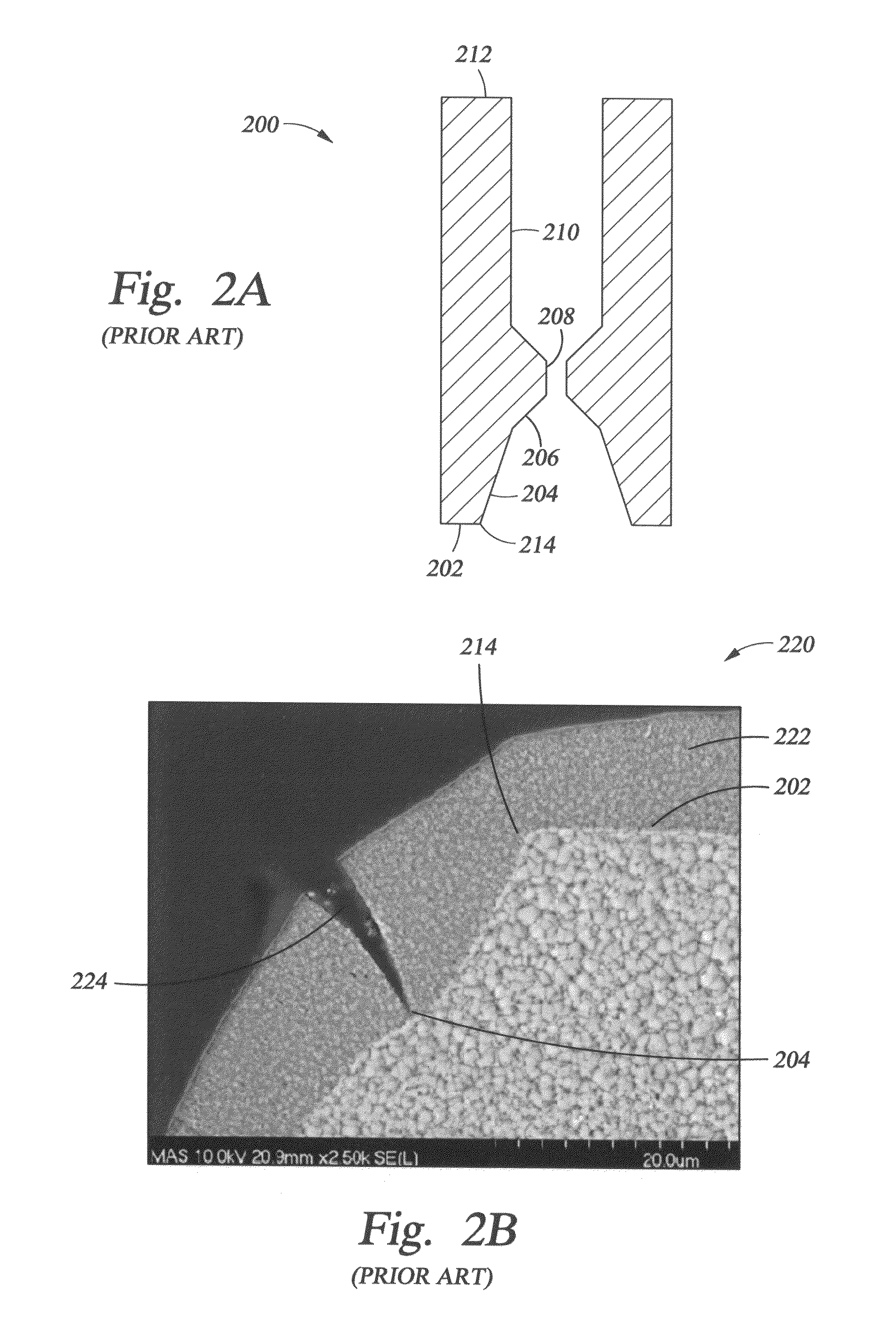
However, due to the relatively sharp corner radii of the gas-supplying openings on the surface of the gas diffuser, it is very difficult to generate an anodized coating which exhibits sufficient integrity at such sharp corner radii. FIG. 1 shows a schematic of a typical gas diffuser 100 of the kind used in the fabrication of flat screen displays.
The non-anodized, bare, polished surface of the aluminum / aluminum alloy gas diffuser continues to be exposed to the harsh environment in the PECVD deposition chamber and is under attack by the PECVD precursor gases and byproducts of the film-forming reactions.

Method used


Image

  • Particle reduction on surfaces of chemical vapor deposition processing apparatus
  • Particle reduction on surfaces of chemical vapor deposition processing apparatus
  • Particle reduction on surfaces of chemical vapor deposition processing apparatus

Examples


example one

[0066]A diffuser cone exterior surface surrounding the cone-shaped exit holes was bead blasted, to achieve a 70 μ-in. Ra finish on flats and inside cone holes using the following parameters:[0067]a. a 120 grit aluminum oxide, 99.5% purity, white[0068]b. Nozzle angle to cone side face: 90±5 degrees[0069]c. Nozzle distance from cone side: 12.0±1.0″[0070]d. Nozzle traverse velocity: 3.0±1.0″ / sec.[0071]e. Nozzle step increment: 2.0±0.5″[0072]f. Nozzle supply pressure: 70±2 psi[0073]g. Direction of travel: X-Y (as illustrated in FIG. 8B)[0074]h. Serpentine path of travel: The direction of each pass shall be opposite to the previous pass so as to produce a back and forth serpentine motion of the nozzle relative to the part. Use sufficient passes so as to cover entire part with a random surface appearance. Visible cosmetic variations such as lines, bands, or zones are not acceptable.[0075]i. Each pass start & stop: Each pass shall start a sufficient distance before the part boundary and sh...

example two

[0079]In a second aluminum alloy surface treatment process, a process chamber liner was bead blasted to obtain a 205±15 μ-inch surface. The aluminum oxide media was 35-46 grit, 99.5% purity white aluminum oxide. The abrasive bead blasting was done as a series of parallel nozzle passes, separated by a fixed horizontal step increment using automated robotic equipment of the kind known in the industry. FIGS. 9A and 9B illustrate the bead blasting configurations relative to the liner substrate 902 which was bead blasted. In the FIG. 9A configuration 900, a bead blasting nozzle 904 of the kind known in the art was positioned above the surface 903 of substrate 902 at a nozzle height 906 of about 5 inches. The nozzle angle α905 was typically about 45° to about 47° relative to the surface 903 of substrate 902. In FIG. 9B, the configuration 920 shows the path of the nozzle 904 over the substrate 902. The horizontal step increment (distance between parallel nozzle passes 922) was typically ab...


PUM

PropertyMeasurementUnit
surface areaaaaaaaaaaa
thicknessaaaaaaaaaa

Abstract

A method of reducing the amount of particulates generated from the surface of a processing component used during plasma enhanced chemical vapor deposition of thin films. The body of the processing component comprises an aluminum alloy, and an exterior surface of said processing component is texturized to increase the amount of surface area present on the exterior surface. The texturizing process includes at least one step in which the surface to be texturized is bead blasted or chemically grained, so that the surface roughness of the texturized surface ranges from about 50 μ-inch Ra to about 1,000 μ-inch Ra.

Description

RELATED APPLICATIONS[0001]This application is related to the following U.S. Patent Applications: U.S. application Ser. No. 11 / 021,416, filed Dec. 22, 2004, which is currently pending; U.S. application Ser. No. 10 / 962,936, filed Oct. 12, 2004, which is currently pending; U.S. application Ser. No. 10 / 897,775, filed Jul. 23, 2004, which is currently pending; U.S. application Ser. No. 10 / 889,683, filed Jul. 12, 2004, which is currently pending; U.S. application Ser. No. 10 / 829,016, filed Apr. 20, 2004, which is currently pending; and, U.S. Provisional Application Ser. No. 60 / 570,876, filed May 12, 2004. Each of the aforementioned applications are hereby incorporated by reference in their entireties. Priority is claimed under U.S. Provisional Application Ser. No. 60 / 763,105, filed Jan. 27, 2006.BACKGROUND OF THE INVENTION[0002]1. Field of the Invention[0003]The invention generally relates to a method of controlling particulates generated on the surface of a gas diffuser used during plasm...

Claims


Application Information

Patent Timeline
Patent Type & Authority Patents(United States)
IPC IPC(8): H05H1/24B05D3/00B05C13/00
CPCB24C1/003B24C3/322
Inventor CHOI, SOO YOUNGWHITE, JOHN M.PARK, BEOM SOOYIM, DONG KIL
Owner APPLIED MATERIALS INC
Why Eureka
Try Eureka