Image processing system with an information transmitting system, image processing device and data processing program therefor

a technology of information transmission system and image processing device, applied in the field of data processing system, can solve the problems of unnecessari consumption of the waiting time period for the server to receive the command request from the client, communication error, and inability to transmi

Active Publication Date: 2012-05-08
BROTHER KOGYO KK
View PDF33 Cites 6 Cited by
  • Summary
  • Abstract
  • Description
  • Claims
  • Application Information

AI Technical Summary

Benefits of technology

[0011]Aspects of the invention provide a network system in which a waiting period of the client for receipt of command / data transmitted from the server is reduced.
[0012]Further aspects of the invention provide a network system in which command / data can be exchanged smoothly without modifying the setting of a network relaying device (e.g., the broadband router) connecting the LAN and the global network (e.g., the Internet).

Problems solved by technology

If no response is issued by the server within a predetermined timeout period, it is determined that a communication error has occurred even if the server does not have any problem.
Further, if there is a command to be transmitted from the server to the client, it cannot be transmitted until the server receives the command request from the client.
Therefore, in comparison with a case where the server can immediately transmit a command, a waiting time period for which the server waits for receipt of the command request from the client should be consumed unnecessarily.
However, to increase the transmission frequency results in increase of network traffic, and thus, the frequency cannot be increased unlimitedly.
However, to change the setting of the router is relatively troublesome, and more importantly, requires the user to change security policy, which may cause a problem.

Method used


Image

  • Image processing system with an information transmitting system, image processing device and data processing program therefor
  • Image processing system with an information transmitting system, image processing device and data processing program therefor
  • Image processing system with an information transmitting system, image processing device and data processing program therefor

Examples


embodiments

[0111]Data processing unit (e.g., image processing system) according to embodiments of the invention will be described, referring to the accompanying drawings.

first embodiment

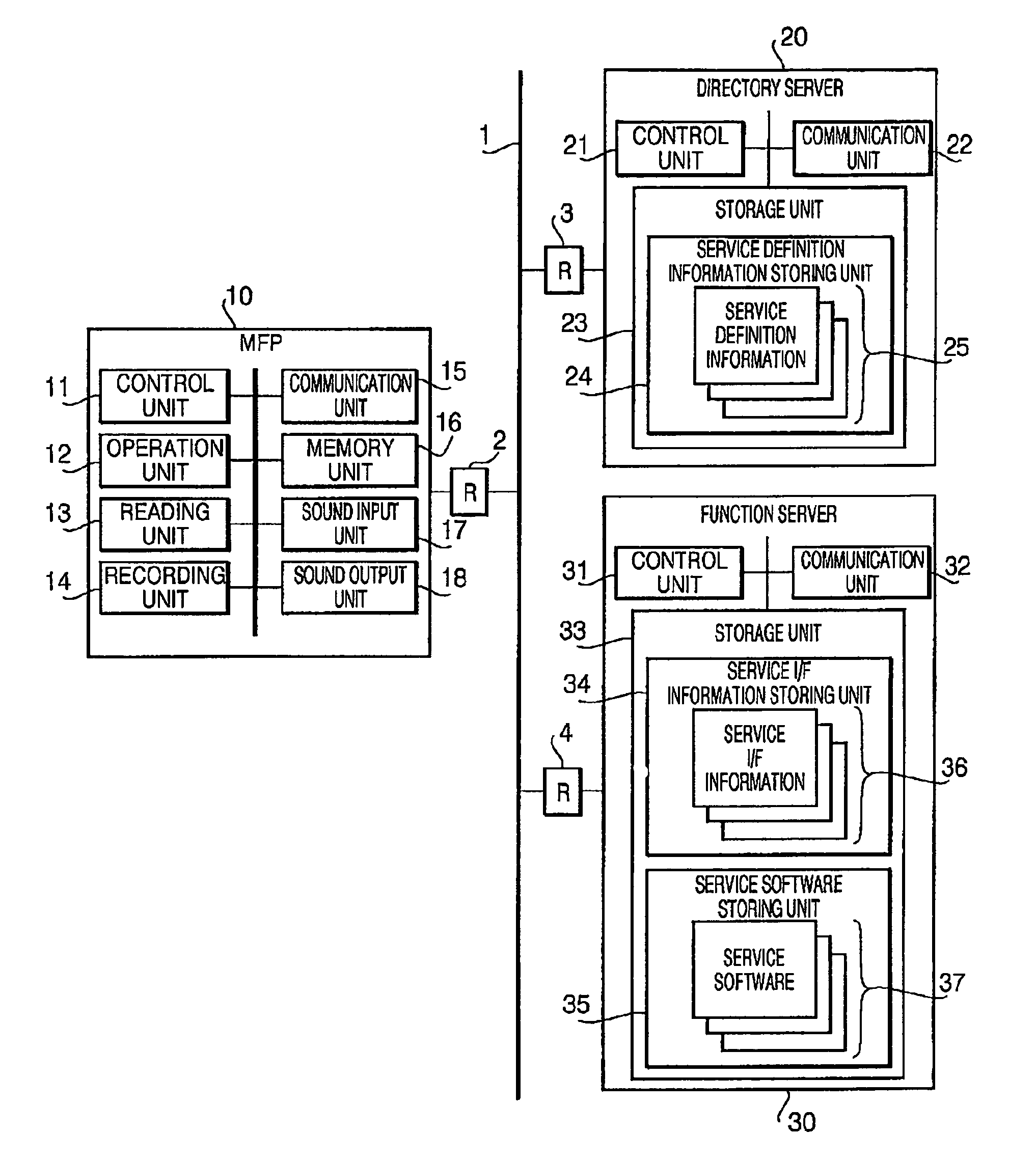
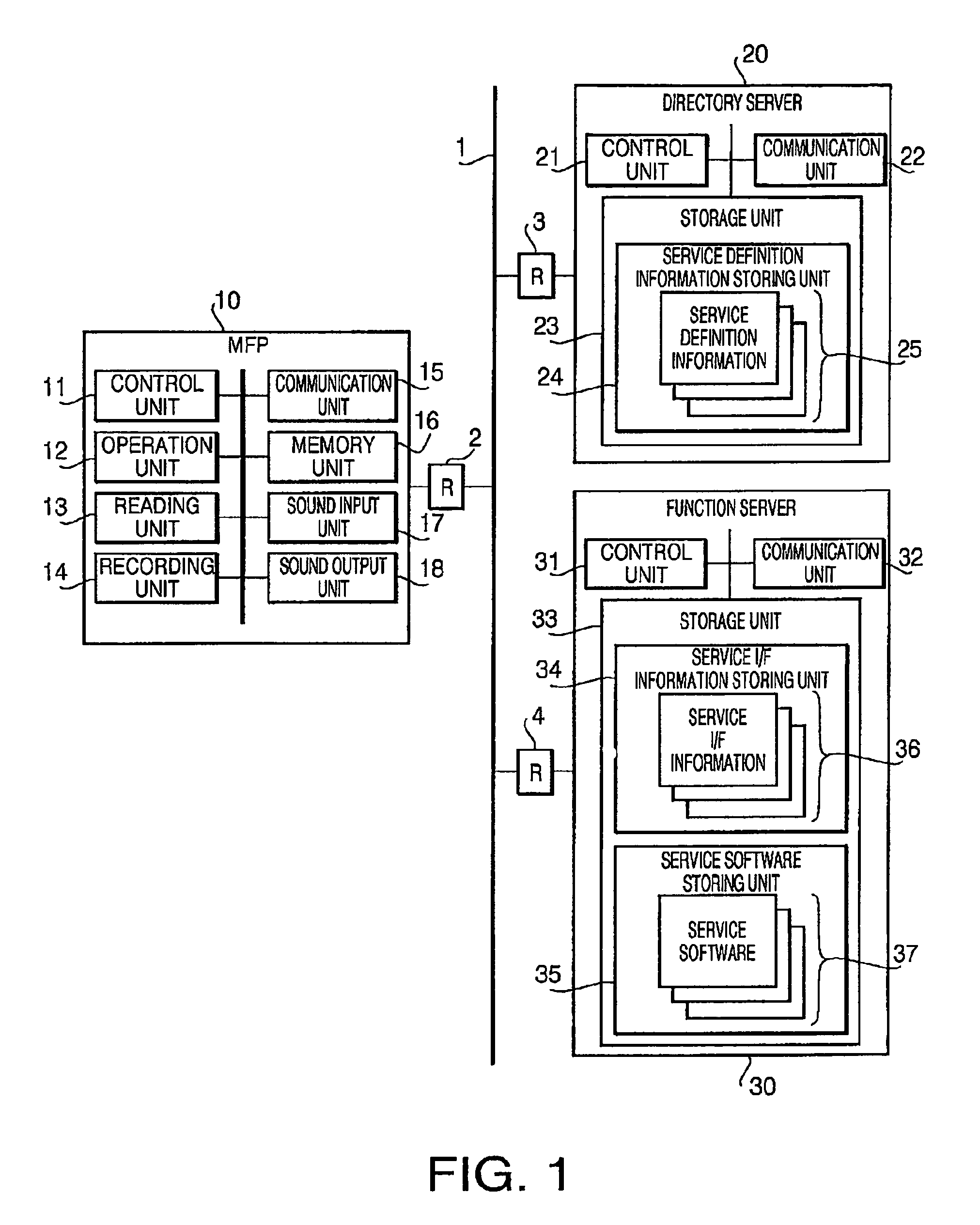
[0112]FIG. 1 is a block diagram showing a configuration of a data processing system according to the invention.

[0113]As shown in this drawing, this data processing system includes an MFP (multiple function peripheral) 10, a directory server 20, and a function server 30, which are connected so that a bidirectional communication via a network 1 (in the present embodiment, a Wide Area Network (WAN) such as the Internet) is available. Specifically, the MFP 10, the directory server 20 and the function server 30 are connected to the network 1, respectively, via routers (R) 2, 3 and 4. The router 2 which connects the MFP 10 and the network 1 is a known broadband router. Under the normal setting (default setting), all ports within this broadband router 2 are closed and, when a connection request is made from an internal source to an external destination (from the MFP 10 side to the network 1 side), only a packet which is compatible as a response to this request is allowed to pass. In other ...

second embodiment

[0466]Next, a data processing system according to a second embodiment will be described. In the second embodiment, the maximum holding period is adjusted in accordance with the congestion of the network.

[0467]The configuration and processes to be executed of the second embodiment are substantially the same. It should be noted that the session process executed by the control unit 11 of the MFP 10 of the second embodiment is different from that of the first embodiment.

[0468]Hereinafter, the session process according to the second embodiment will be described with reference to FIG. 31. In comparison with the session process according to the session process (FIG. 14), S231 is executed instead of S204, and S212 and S216 are omitted. In FIG. 31, to the step similar to those of FIG. 14, the same step numbers are assigned and detailed description will not be repeated. Further, steps S221-S228 are identical to those in FIG. 15.

[0469]When the session process shown in FIG. 31 is started, the p...


PUM


Abstract

In a communication system having a client and a server capable of communicating with each other via a network, the server can transmit a command to the client in response to a command request transmitted from the client to the server. The server may include a replying unit that transmits replaying data in response to the command received from the client in such a manner that (a) if there is a command to be transmitted to the client, replying data including the command is transmitted to the client, and (b) if there is not a command to be transmitted to the client, replying data, which does not include a command is transmitted to the client. Further, the replying unit may transmit the replying data without a command to the client when a no-command status lasts a predetermined standby period after receipt of the command request.

Description

INCORPORATION BY REFERENCE[0001]This application claims priority from Japanese Patent Applications No. 2004-322934 and No. 2004-322935, both filed on Nov. 5, 2004, the entire subject matters of which are incorporated herein by reference.BACKGROUND OF THE INVENTION[0002]1. Technical Field[0003]The present invention relates to a data processing system having a server and terminal devices interconnected through a network.[0004]2. Description of Related Art[0005]Conventionally, a system configured such that a client (e.g., a digital copier, a scanner, a multi function peripheral) connected to a LAN (Local Area Network) and a host computer (i.e., a server) are interconnected through a global network (e.g., the Internet). Particularly, there is known a system, wherein the host computer achieves a function that the client does not have instead of the client. An example of such a system is disclosed in Japanese Patent Provisional Publication No. HEI 9-238215.[0006]In a general communication...

Claims


Application Information

Patent Timeline
Patent Type & Authority Patents(United States)
IPC IPC(8): G06F3/12G06F15/00
CPCH04N1/00209H04N1/00244H04N1/00281H04N2201/001H04N2201/3212H04N2201/3222
Inventor YANAGI, SATORUAOKI, KAZUMAKOKUBO, MASATOSHIOTSUKA, NAOKIMATSUDA, MAKOTOMIYAZAWA, MASAFUMIOHARA, KIYOTAKA
Owner BROTHER KOGYO KK
Why Eureka
Try Eureka