
Magnetic random access memory and initializing method for the same

a random access memory and initialization method technology, applied in the field of magnetic random access memory of domain wall motion type, can solve the problems of difficult to initialize the magnetization state to a desired state by using an external magnetic field, and the absolute value of the write current becomes relatively large, so as to achieve low cost, easy initialization of the magnetization state, and low cost

Active Publication Date: 2012-05-08
NEC CORP
View PDF15 Cites 12 Cited by
  • Summary
  • Abstract
  • Description
  • Claims
  • Application Information

AI Technical Summary

Benefits of technology

The patent text describes a new type of MRAM that uses perpendicular magnetic anisotropy material to move domain walls in a magnetic recording layer. The technical effect of this is that the write current required for the MRAM is reduced. However, there is a challenge in initializing the magnetization state of the magnetic recording layer to a desired state using an external magnetic field. The patent text proposes a solution by providing a magnetic recording layer with a first magnetization region, a second magnetization region, and a magnetization switching region that has reversible magnetization. An initializing method is also provided to fix the magnetization direction of the first and second magnetization regions in opposite directions and create a pair of domain walls in the magnetization switching region. This new MRAM and method offer a way to reduce the write current and improve the efficiency of the MRAM.

Problems solved by technology

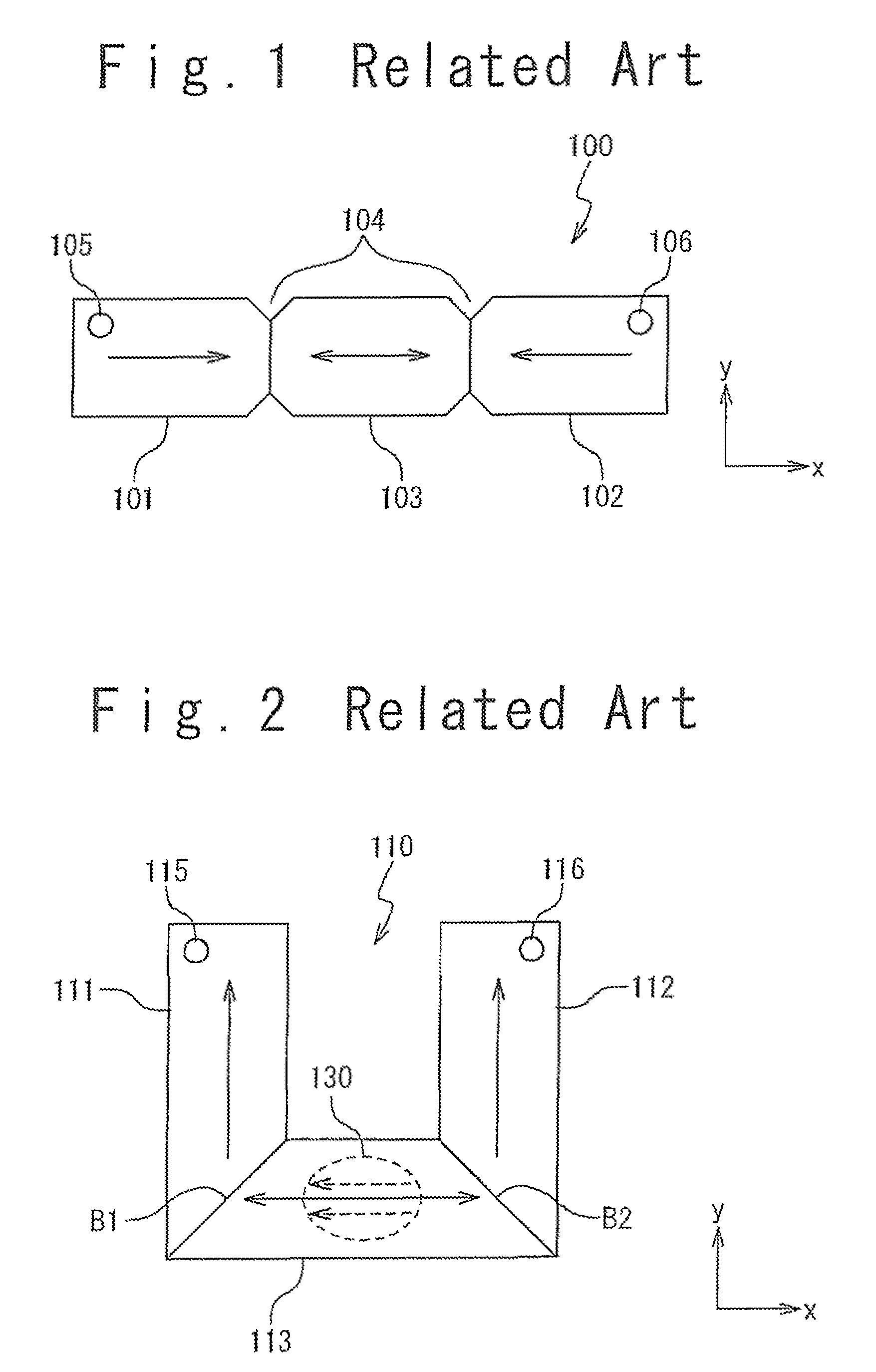
In the case of the above-mentioned MRAM using the current-driven domain wall motion, there is fear that an absolute value of the write current becomes relatively large.
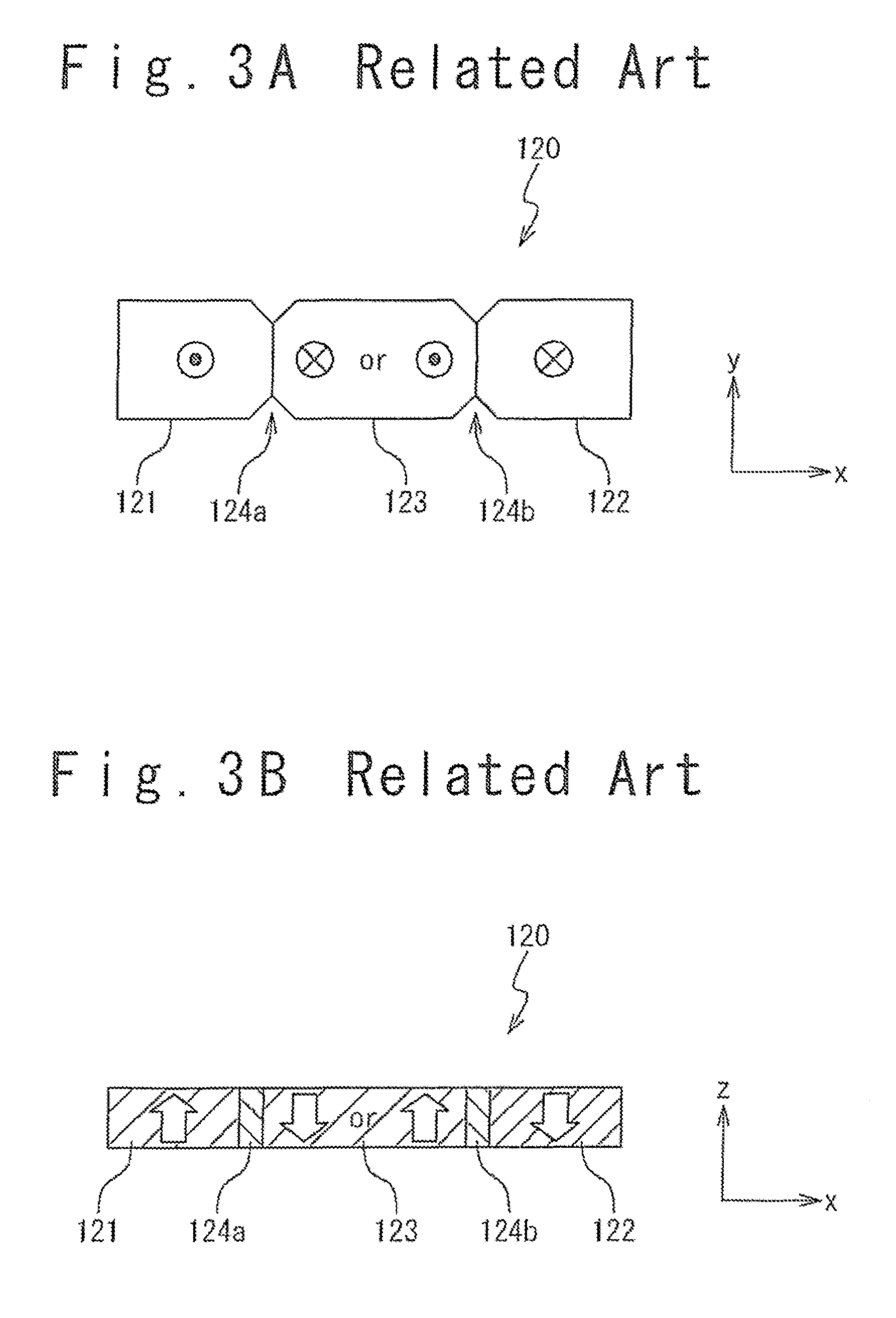
In the case of the perpendicular magnetic anisotropy, however, it is difficult to initialize the magnetization state to a desired state by using an external magnetic field, even when the magnetic recording layer has the U-shape.

Method used


Image

  • Magnetic random access memory and initializing method for the same
  • Magnetic random access memory and initializing method for the same
  • Magnetic random access memory and initializing method for the same

Examples


modification examples

4. Modification Examples

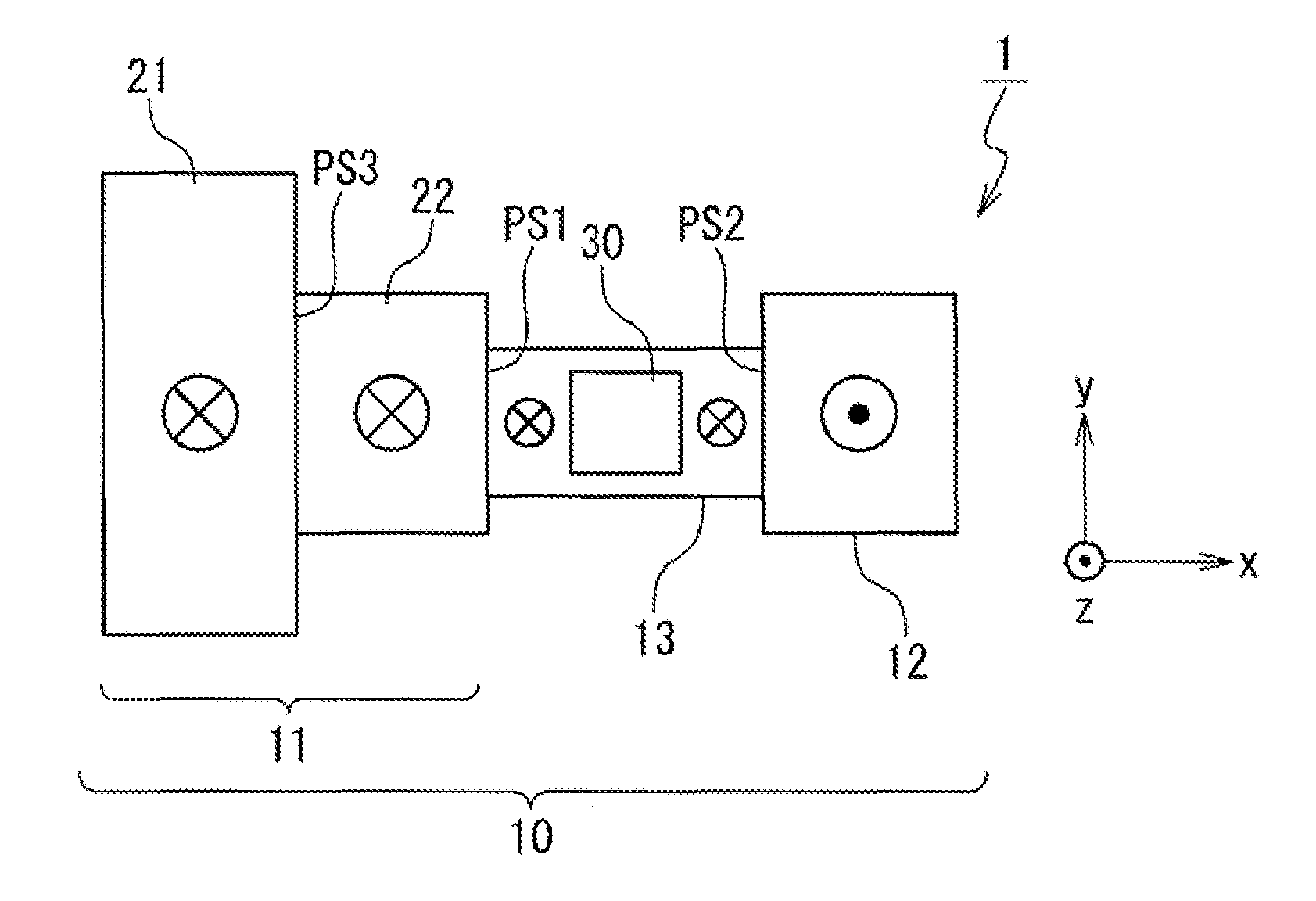
[0069]A structure that can achieve the initializing method according to the present exemplary embodiment is not limited to the one shown in the foregoing FIGS. 4A and 4B. FIGS. 7, 8, 9, 10A and 10B show modification examples of the magnetic memory cell 1 according to the present exemplary embodiment. A description overlapping the foregoing description will be omitted as appropriate.

[0070]In FIG. 7, a width in the Y direction of the first region 21 becomes larger as way from the boundary between the first region 21 and the second region 22 towards inside of the first region 21. That is, the magnetic recording layer 10 is formed such that the width of the first region 21 becomes gradually larger as compared with the width of the second region 22. As a result, the third pinning site PS3 satisfying the above-mentioned relational expressions regarding the depinning magnetic field is formed at the boundary between the first region 21 and the second region 22.

[0071]...


PUM


Abstract

A domain wall motion type MRAM has: a magnetic recording layer 10 having perpendicular magnetic anisotropy; and a pair of terminals 51 and 52 used for supplying a current to the magnetic recording layer 10. The magnetic recording layer 10 has: a first magnetization region 11 connected to one of the pair of terminals; a second magnetization region 12 connected to the other of the pair of terminals; and a magnetization switching region 13 connecting between the first magnetization region 11 and the second magnetization region 12 and having reversible magnetization. A first pinning site PS1, by which the domain wall is trapped, is formed at a boundary between the first magnetization region 11 and the magnetization switching region 13. A second pinning site PS2, by which the domain wall is trapped, is formed at a boundary between the second magnetization region 12 and the magnetization switching region 13. A third pinning site PS3, by which the domain wall is trapped, is formed within the first magnetization region 11.

Description

TECHNICAL FIELD[0001]The present invention relates to a domain wall motion type magnetic random access memory (MRAM: Magnetic Random Access Memory). In particular, the present invention relates to a domain wall motion type MRAM using a magnetic layer having perpendicular magnetic anisotropy, and a method of initializing the same.BACKGROUND ART[0002]An MRAM is a promising nonvolatile memory from a viewpoint of high integration and high-speed operation. In the MRAM, a magnetoresistance element that exhibits a “magnetoresistance effect” such as TMR (Tunnel MagnetoResistance) effect is utilized. In the magnetoresistance element, for example, a magnetic tunnel junction (MTJ: Magnetic Tunnel Junction) in which a tunnel barrier layer is sandwiched by two ferromagnetic layers is formed. The two ferromagnetic layers include a magnetization fixed layer (pinned layer) whose magnetization direction is fixed and a magnetization free layer (free layer) whose magnetization direction is reversible....

Claims


Application Information

Patent Timeline
Patent Type & Authority Patents(United States)
IPC IPC(8): G11C11/00G11C11/14G11C11/15
CPCG11C11/15H01L43/08H01L27/228G11C11/1659G11C11/161G11C11/1673G11C11/1675H10B61/22H10N50/10
Inventor SUZUKI, TETSUHIROFUKAMI, SHUNSUKEOHSHIMA, NORIKAZUNAGAHARA, KIYOKAZUISHIWATA, NOBUYUKI
Owner NEC CORP
Learn More