Control device for multi-stage turbochargers

a control device and turbocharger technology, applied in the direction of electric control, positive displacement liquid engines, machines/engines, etc., can solve the problems of affecting the efficiency of the engine, the inability to achieve the boost that was naturally and sufficiently obtained in the stationary operation of the engine, and the inability to achieve the boost in a transient mode. achieve the effect of improving fuel consumption

Active Publication Date: 2012-05-15
ISUZU MOTORS LTD
View PDF14 Cites 63 Cited by
  • Summary
  • Abstract
  • Description
  • Claims
  • Application Information

AI Technical Summary

Benefits of technology

[0020]Thus, as shown in FIG. 5, the pressure increase of the entire two-stage turbo system can be accelerated with respect to that of a single turbo.
[0032]The present invention demonstrates an excellent effect of enabling the improvement of fuel consumption in transient and stationary states of an engine equipped with multi-stage turbochargers.

Problems solved by technology

However, the problem associated with the two-stage turbo system is that a pressure increase lag occurs in a turbocharger disposed in a low-pressure stage (rear stage) in a rise period e.g. in a transient test mode.
Thus, a boost that was naturally and sufficiently obtained in engine stationary operation cannot be sufficiently attained in a transient mode.

Method used


Image

  • Control device for multi-stage turbochargers
  • Control device for multi-stage turbochargers
  • Control device for multi-stage turbochargers

Examples


Embodiment Construction

[0048]A preferred embodiment of the present invention will be described below with reference to the appended drawings.

[0049]A control device for multi-stage turbochargers of the present embodiment is designed, for example, for a two-stage turbo system mounted on a diesel engine (referred to hereinbelow as “engine”) of a vehicle.

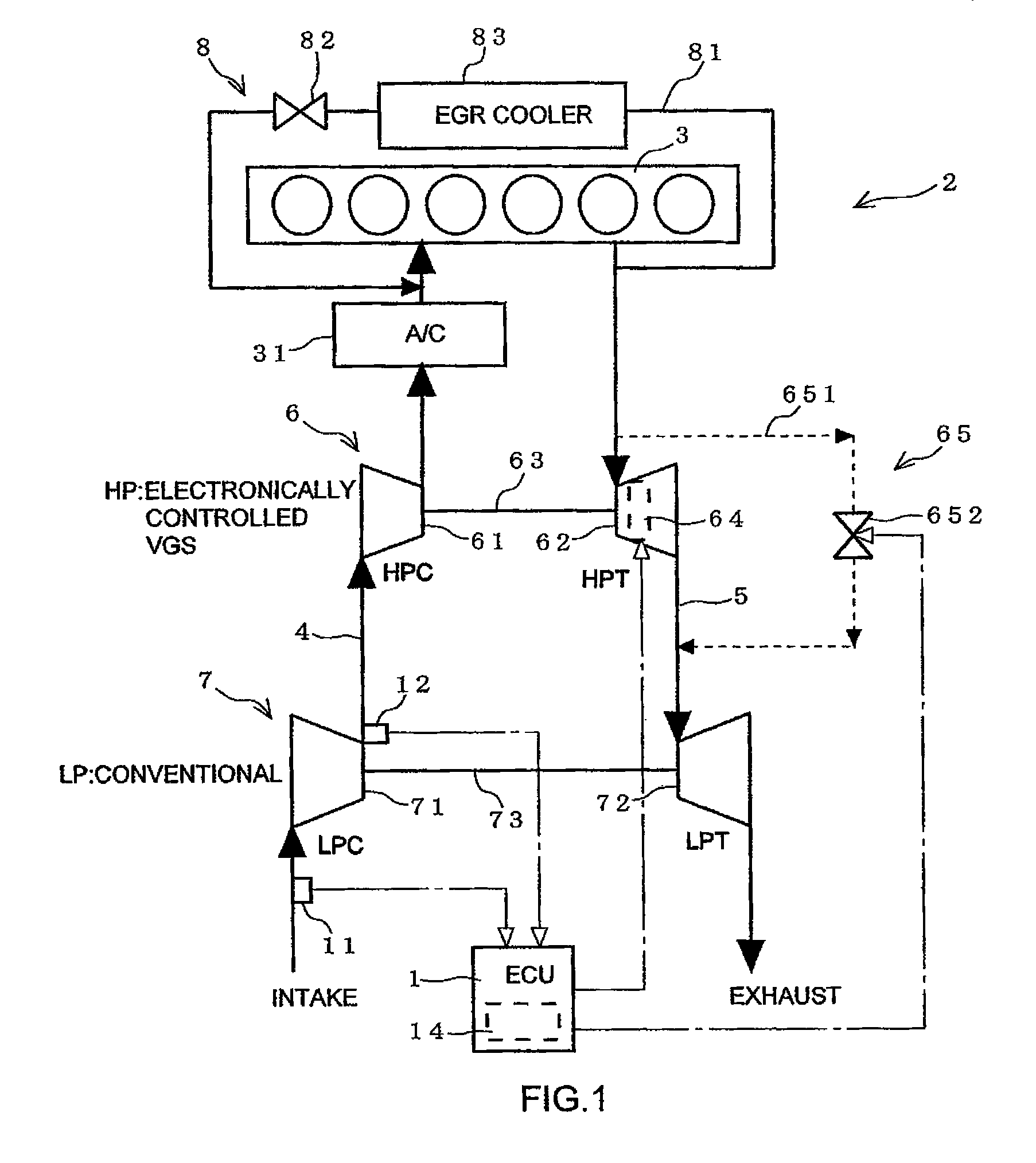
[0050]A schematic structure of the engine will be described based on FIG. 1.

[0051]As shown in FIG. 1, an engine 2 includes an engine body 3 having a plurality of cylinders, an intake passage 4 and an exhaust passage 5 connected to the engine body 3, turbochargers 6, 7 provided in the intake passage 4 and the exhaust passage 5 and serving to supply supercharged air to the engine body 3, an EGR device 8 for returning part of exhaust gas of the exhaust passage 5 to the intake passage 4, and an engine control unit (referred to hereinbelow as ECU) 1 for controlling the engine body 3.

[0052]In the present embodiment, the high-pressure stage turbocharger (HP) 6 and t...


PUM


Abstract

A control device for multi-stage turbochargers is provided that is capable of improving fuel consumption in transient and stationary states of an engine equipped with multi-stage turbochargers. A control device 1 for multi-stage turbochargers which are turbochargers 6, 7 of at least two or more stages provided in series at an engine 2 and in which the high-pressure stage turbocharger 6 is configured by a variable-capacity turbocharger 6 equipped with a variable vane 64 comprising detection means 11, 12 for detecting a boost pressure or an intake air amount of a turbocharger 7 of a stage with a pressure lower than that of the variable-capacity turbocharger 6, the opening degree of the variable vane 64 being controlled on the basis of a detection value of the detection means 11, 12.

Description

CROSS REFERENCE TO RELATED APPLICATIONS[0001]This application is entitled to the benefit of and incorporates by reference essential subject matter disclosed in International Patent Application No. PCT / JP2007 / 067485 filed on Sep. 7, 2007 and Japanese Patent Application No. 2006-245401 filed Sep. 11, 2006.TECHNICAL FIELD[0002]The present invention relates to a control device for multi-stage turbochargers in which turbochargers of at least two stages are provided in series.BACKGROUND[0003]In recent years, exhaust gas standards for automobile engines have been getting more stringent from year to year, methods for engine evaluation have also been getting more demanding, and methods for performing evaluation during start and acceleration have been introduced. As specific evaluation methods, a JE05 mode has been implemented in Japan and an ETC mode has been implemented in Europe (EC).[0004]Exhaust gas standards widely use nitrogen oxide (referred to hereinbelow as NOx) and diesel particula...

Claims


Application Information

Patent Timeline
Patent Type & Authority Patents(United States)
IPC IPC(8): F02B37/013F02B37/00F02B37/12
CPCF02B37/013F02B37/24F02D41/0007F02M25/0711F02B37/004F02B29/0406F02D41/187F02D2200/0406F02M25/0713F02M25/0727Y02T10/144F02M26/08F02M26/10F02M26/23Y02T10/12
Inventor KOMATSU, AKIRA
Owner ISUZU MOTORS LTD
Why Eureka
Try Eureka