Brazed rotary cutting tool, an insert for a brazed rotary cutting tool, and methods for manufacturing the same

a rotary cutting tool and brazing technology, applied in the field of brazing rotary cutting tools, can solve the problems of difficult or impossible production of pcd-tipped rotary cutting tools with fine non-linear geometry along the rake face and tightly toleranced cutting edge profiles and diameters, and compromise the geometry of the rake face or the cutting edge profile, etc., to achieve the effect of convenient maintenance and alignmen

Inactive Publication Date: 2012-05-15
ISAACSON GLENN +1
View PDF4 Cites 25 Cited by
  • Summary
  • Abstract
  • Description
  • Claims
  • Application Information

AI Technical Summary

Benefits of technology

[0022]In accordance with another aspect of this invention, another method for manufacturing a brazeable rotary cutting tool insert is provided. The method includes providing a disk with a plurality of layers, wherein one layer is a carbide layer and another layer is a wear layer. The method further includes forming the insert from the disk, determining the amount of brazing-induced warp along the bottom surface of the insert, and forming a relief in the bottom surface to a depth based, at least in part, on the amount of brazing-induced warp along the bottom surface. This makes it easier to maintain alignment between the insert and the tool body as compared to normally formed inserts which can exhibit a “rocking” single point of contact on the bottom interface during brazing.

Problems solved by technology

Prior to this invention, producing a PCD-tipped rotary cutting tool with fine non-linear geometry along the rake face and a tightly-toleranced cutting edge profile and diameter would have been difficult or impossible.
Because of the problems associated with braze-induced warp, either the geometry of the rake face or the profile of the cutting edge would be compromised when finish grinding or EDM operations were performed to bring the brazed and warped cutting edge into conformity with the desired tool specifications.

Method used


Image

  • Brazed rotary cutting tool, an insert for a brazed rotary cutting tool, and methods for manufacturing the same
  • Brazed rotary cutting tool, an insert for a brazed rotary cutting tool, and methods for manufacturing the same
  • Brazed rotary cutting tool, an insert for a brazed rotary cutting tool, and methods for manufacturing the same

Examples


Embodiment Construction

1. Prior Art

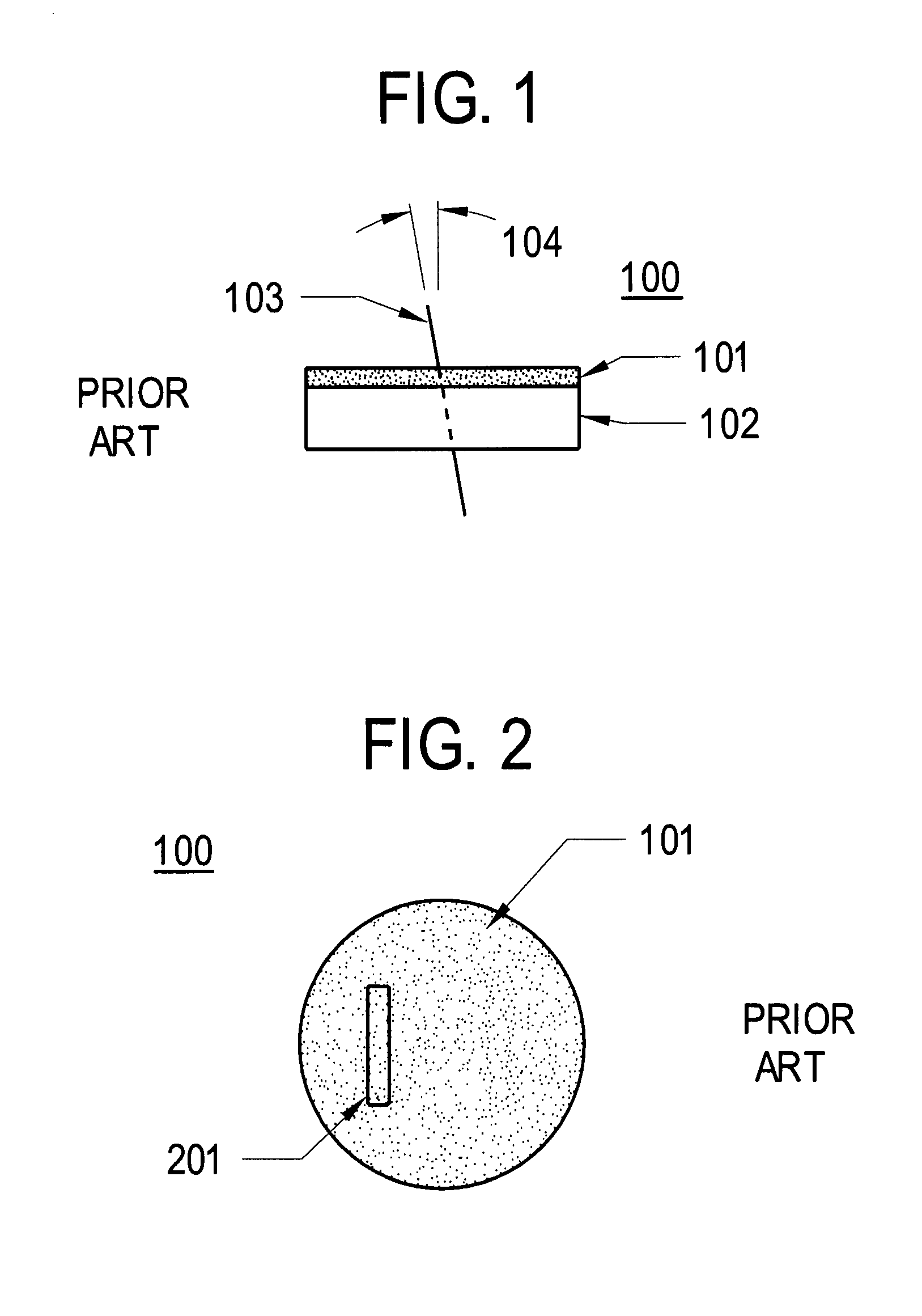
[0042]FIG. 1 is a side elevation view showing a typical prior art PCD and carbide disk 100 with an EDM wire 104 passing through the disk and is discussed in the background section above.

[0043]FIG. 2 is a top view of the prior art PCD and carbide disk 100 showing exemplary EDM cut paths for a typical prior art insert 201 shape and is discussed in the background section above.

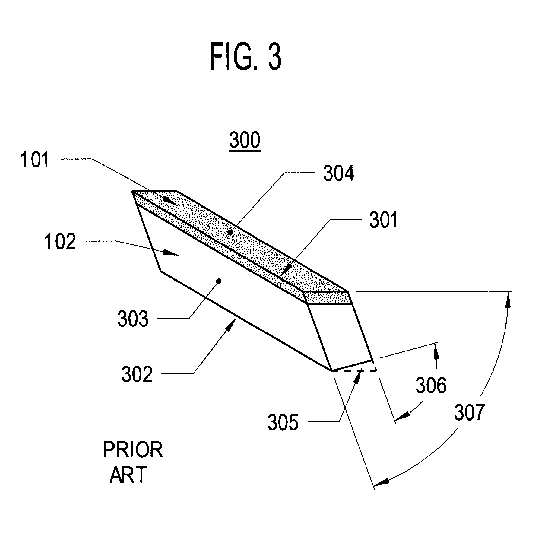
[0044]FIG. 3 is a perspective view of a typical prior art cutting tool insert and is discussed in the background section above.

[0045]FIGS. 4A and 4B are side elevation views of a typical prior art cutting tool, where FIG. 4A shows an insert without distortion and FIG. 4B shows an insert with braze induced distortion and are discussed in the background section above.

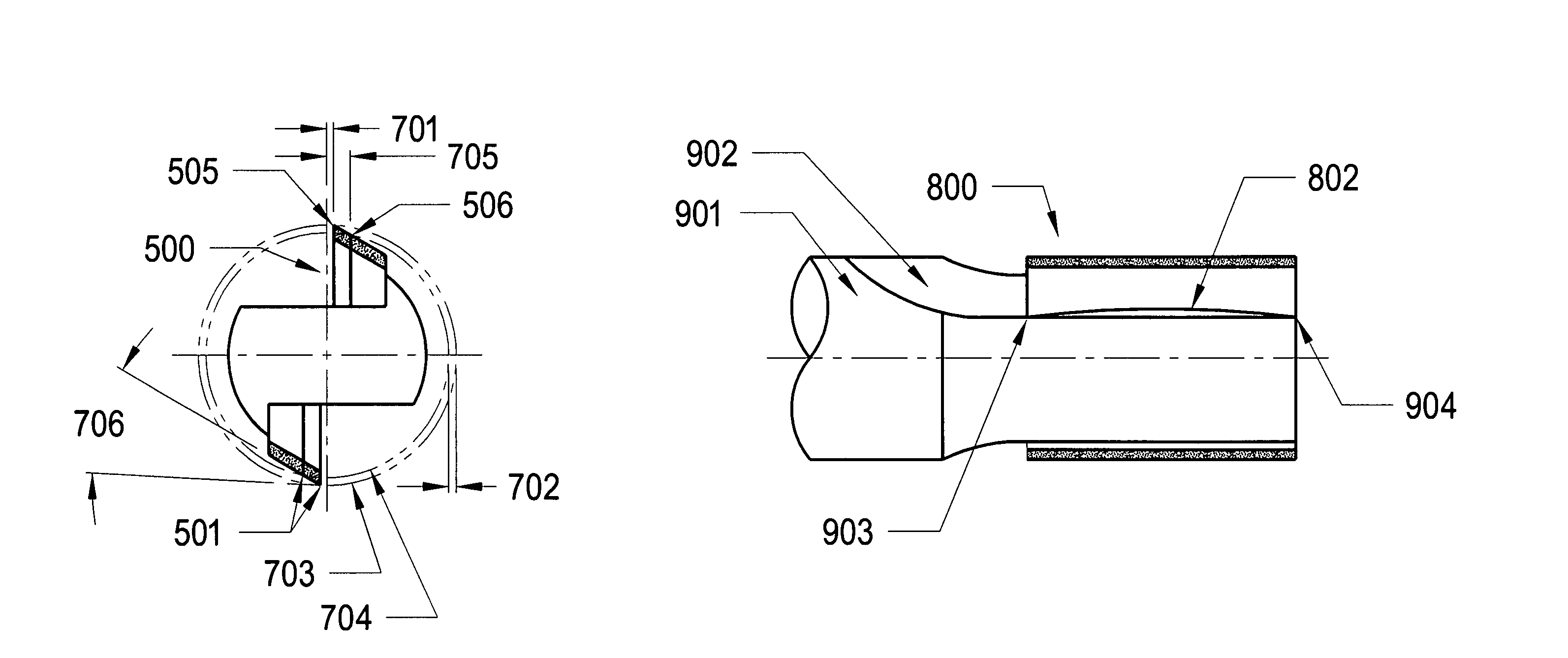
[0046]FIG. 6 is a typical prior art end view of a router bit or endmill type rotary cutting tool and is discussed in detail below.

2. Rake Face and Cutting Edge Bow

[0047]FIG. 13, together with FIG. 4A through FIG. 7, provides a roadmap to a ...


PUM

PropertyMeasurementUnit
angleaaaaaaaaaa
included angleaaaaaaaaaa
shear angleaaaaaaaaaa

Abstract

A method for producing carbide and diamond cutting tool inserts adapted to compensate for braze-induced warp is provided. In this method, the anticipated warpage of the insert from brazing is considered prior to cutting the insert from a PCD and carbide disk and the cutting path for the insert is adjusted to compensate. The adjusted cutting path creates an insert shape that, after warping as a result of the brazing process, will conform substantially to the originally intended insert or cutting tool shape. Also, a method of providing relief on the bottom surface of a brazeable insert is provided. Further, tools produceable by these methods are disclosed, such as a diamond edged rotary cutting tool with a substantially sinusoidal rake face and cutting edge.

Description

PRIORITY OF THE INVENTION[0001]This application claims priority to U.S. Provisional Patent Application Ser. No. 60 / 802,477 filed May 22, 2006, incorporated by reference herein in its entirety.FIELD OF THE INVENTION[0002]The present invention relates generally to rotary cutting tools and the manufacture thereof, and more particularly, to the manufacture and use of pre-warped carbide and diamond inserts for the construction of brazed rotary cutting tools.BACKGROUND[0003]Brazed rotary cutting tools include, but are not limited to: endmills, router bits, shapers, drills, reamers, counterbores, countersinks, and taps. In designing and using such cutting tools, significant attention is paid to both the wear resistance and to the dimensional precision of a tool. As a result, significant efforts are made to improve those characteristics, while constraining any cost increases such improvements might have upon the construction price of the cutting tools.[0004]Wear resistance is typically affe...

Claims


Application Information

Patent Timeline
Patent Type & Authority Patents(United States)
IPC IPC(8): B23D57/00
CPCB23C5/1081B23H7/02B23H9/00B23C2210/084B23C2210/088B23C2226/315Y10T407/26B23K2201/20Y10T407/1904B23C2240/08B23K2101/20Y10T83/9319Y10T83/9348Y10T83/9365
Inventor ISAACSON, GLENNO'BRIEN, MARK P.
Owner ISAACSON GLENN
Why Eureka
Try Eureka