
System for and method of ensuring accurate shadow mask-to-substrate registration in a deposition process

A deposition system, shadow mask technology, applied in metal material coating process, vacuum evaporation coating, coating and other directions

Inactive Publication Date: 2007-07-11
ADVANTECH GLOBAL LTD
View PDF5 Cites 0 Cited by
  • Summary
  • Abstract
  • Description
  • Claims
  • Application Information

AI Technical Summary

Problems solved by technology

This CTE mismatch creates undesired geometric errors between the shadow mask and substrate during the deposition process

Method used


Image

  • System for and method of ensuring accurate shadow mask-to-substrate registration in a deposition process
  • System for and method of ensuring accurate shadow mask-to-substrate registration in a deposition process
  • System for and method of ensuring accurate shadow mask-to-substrate registration in a deposition process

Examples


Embodiment Construction

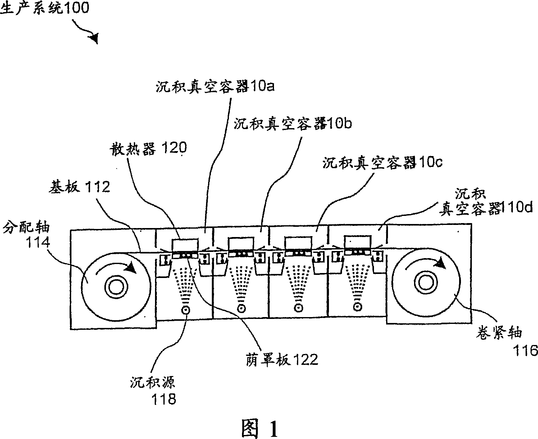
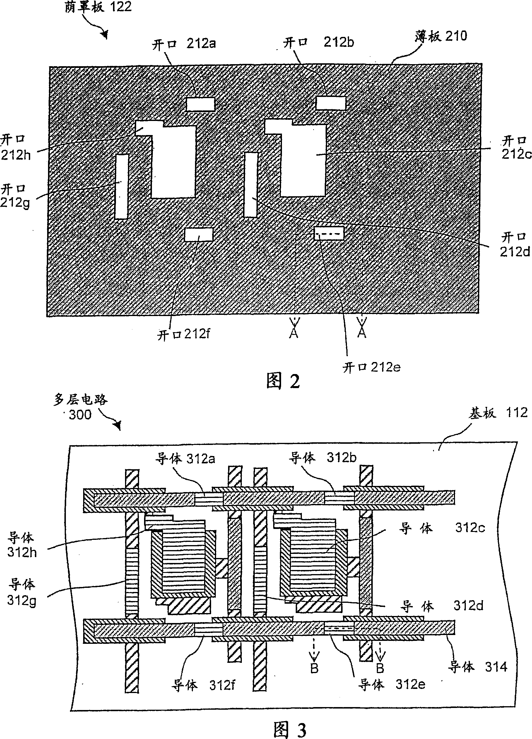
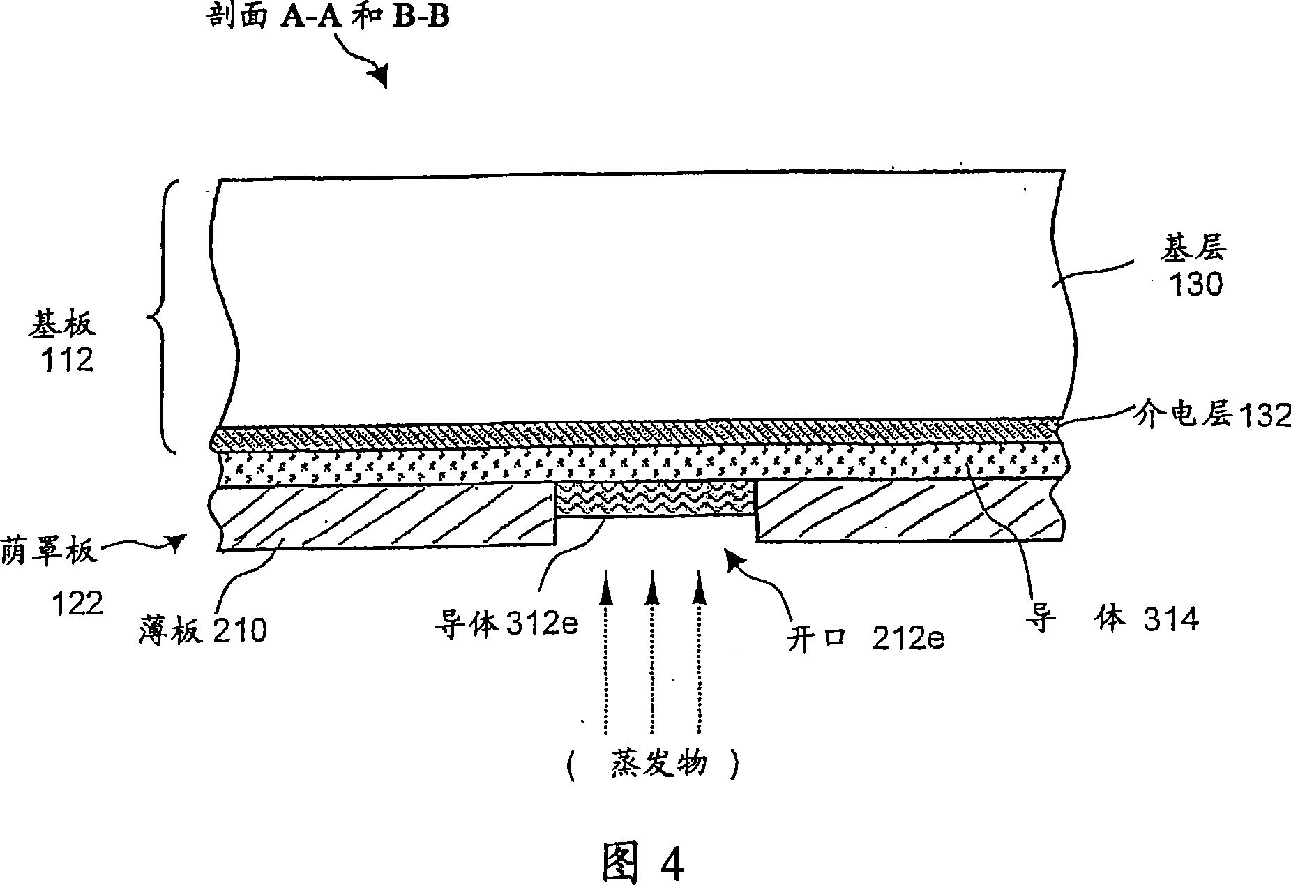
[0024] 1, which shows a production system 100 according to the present invention, the production system 100 by utilizing shadow mask and substrate materials with similar CTE values ​​to ensure accurate alignment of the shadow mask and the substrate, so that thermal effects caused by Any misregistration between the two is minimized. Production system 100 represents a system for producing electronic devices, such as having active matrix backplanes on which organic light emitting diodes (OLEDs) are deposited.

[0025]A non-limiting exemplary production system 100 is described in U.S. Patent No. 2003 / 0228715 entitled "Active Matrix Backplane For Controlling Controlled Elements And Method Of Manufacture Thereof" described in the application publication, which is hereby incorporated by reference. The '715 publication describes electronic devices formed from electronic components deposited onto a substrate. The electronic components are deposited on the substrate by pushing the sub...


PUM

PropertyMeasurementUnit
densityaaaaaaaaaa
Curie pointaaaaaaaaaa
densityaaaaaaaaaa

Abstract

A deposition system uses the same low coefficient of thermal expansion (CTE) material, for example, a CTE of below 10 ppm / DEG C in the temperature range of 0-200 DEG C, for forming both a shadow mask and a substrate upon which depositions occur in order to overcome the heating effects of a high-temperature deposition process, thereby ensuring a uniform expansion and contraction rate of the shadow mask and the substrate.

Description

technical field [0001] This invention relates to shadow masks for forming electronic components on substrates, and more particularly to ensuring accurate registration of shadow masks to substrates in high temperature deposition production systems. Background technique [0002] Active matrix backplanes are widely used in flat panel displays to send signals to the individual pixels of the display to create a viewable image. Currently, the active matrix backplanes used in flat panel displays are formed by photolithographic manufacturing processes, driven by the demand for higher and higher resolution displays in the market, and no other manufacturing process is possible. Photolithography is a pattern definition technique that uses electromagnetic radiation, such as ultraviolet radiation, to expose a resist layer deposited on the surface of a substrate. The steps of an exemplary photolithography process for producing an active matrix backplane include: coating photoresist, preb...

Claims


Application Information

Patent Timeline
Patent Type & Authority Applications(China)
IPC IPC(8): H01L21/44
CPCC23C14/042C23C14/562
Inventor 托马斯·彼得·布罗迪
Owner ADVANTECH GLOBAL LTD
Learn More