Continuous carbonation apparatus and method

a carbonation apparatus and continuous technology, applied in the field of gas dissolution, can solve the problems of many problems encountered in small scale carbonating apparatuses, the production of high-quality carbonated water becomes more problematic, and the conventional system that produces carbonated water suffers from several critical problems, so as to achieve a high degree of surface area and the effect of greater efficiency in dissolving one substan

Inactive Publication Date: 2012-05-15
NATURA WATER
View PDF22 Cites 37 Cited by
  • Summary
  • Abstract
  • Description
  • Claims
  • Application Information

AI Technical Summary

Benefits of technology

[0010]It is widely appreciated that greater efficiency in dissolving one substance in another may be had where both substances have a high degree of surface area with which to interact. In the arena of water carbonation this is oft...

Problems solved by technology

However, the production of high-quality carbonated water becomes more problematic when time and space constraints are imposed on the carbonation apparatus, as is the case with, for example, restaurant beverage vending or in-home carbonated water dispensers.
Many issues are encountered with small scale carbonating apparatus.
These range from problems regulating liquid and gas flow rates to spitting and sputtering which occurs upon initial operation due to a build up of pressure caused in part by the separation of gas and liquid upon standing for a period of time.
Conventional systems that produce carbonated water suffer from several critical problems.
Generally, those are expense, size, and c...

Method used


Image

  • Continuous carbonation apparatus and method
  • Continuous carbonation apparatus and method
  • Continuous carbonation apparatus and method

Examples


Embodiment Construction

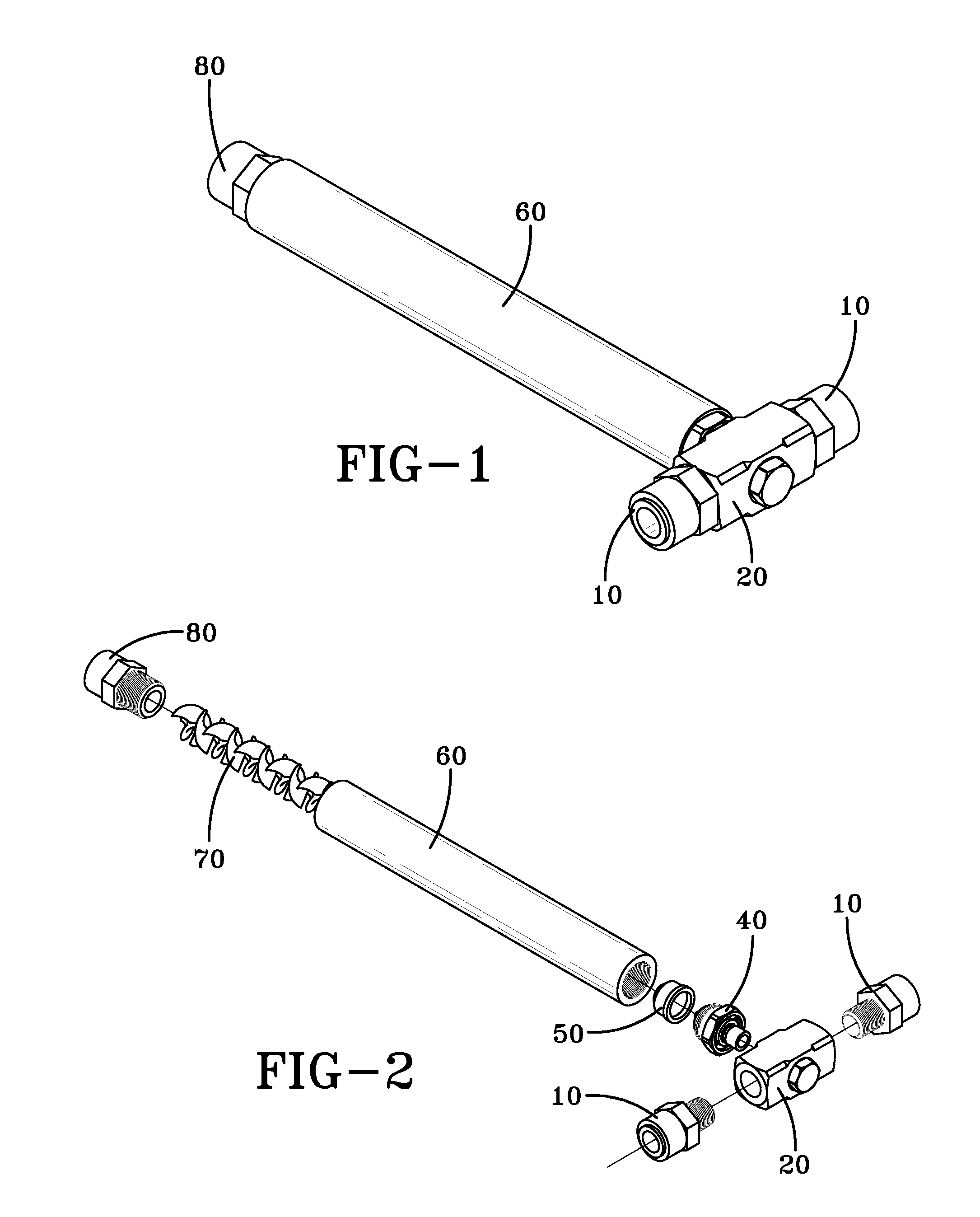
[0027]Turning to the drawings for a better understanding, FIG. 1 shows a perspective view of an embodiment of the assembled apparatus. It can be appreciated from this depiction that the apparatus is not as bulky or complicated as conventional carbonation apparatuses.

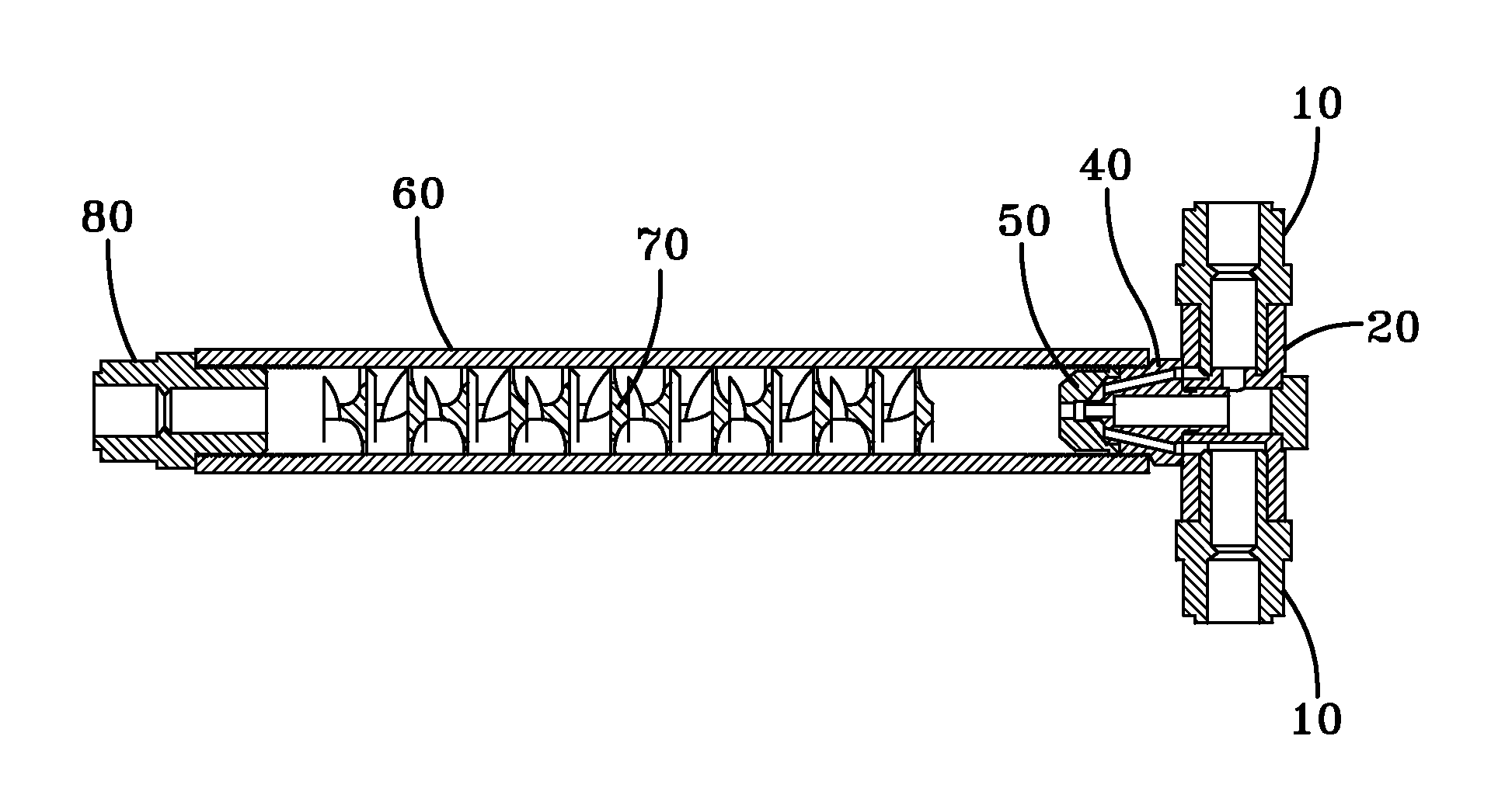
[0028]FIG. 1 is a perspective view of an embodiment of a compact continuous water carbonation system. FIG. 1 displays several of the components of the system including the optional fluid passage adapters 10, the manifold assembly 20, at the inlet end of a mixing chamber 60, and the optional outlet adapter 80 at the outlet end of the mixing chamber.

[0029]FIG. 2 is an exploded view of the embodiment introduced in FIG. 1. It can be appreciated from FIG. 2 that this embodiment of the apparatus can be disassembled into a relatively small number of necessary parts. As seen from FIG. 2, the compact continuous water carbonation system may include fluid passage adapters 10, in communication with the manifold assembly 20. Addition...


PUM

PropertyMeasurementUnit
Flow rateaaaaaaaaaa
Lengthaaaaaaaaaa
Interactionaaaaaaaaaa

Abstract

The present invention provides a method and compact apparatus for providing a continuous flow of carbonated water. The apparatus atomizes the water into microscopic particles allowing for significantly increased interaction between the water and the carbon dioxide. The water and the carbon dioxide then travel into a mixing chamber where further mixing takes place. The invention does not require the use of a pump or the use of a large carbonator vessel.

Description

CROSS-REFERENCE TO RELATED APPLICATIONS[0001]This non-provisional patent application makes no claim of priority to any earlier filings.TECHNICAL FIELD[0002]The disclosed embodiments of the present invention are in the field of gas dissolution, and relate more particularly to the field of water carbonation.BACKGROUND OF THE ART[0003]Apparatus and methods for mixing gases and liquids and, more particularly, apparatuses for dissolving carbon dioxide in water to produce carbonated water, are well known. The quality of carbonated water depends primarily upon the thoroughness with which carbon dioxide is dissolved in the water.[0004]Conventional systems to produce carbonated water use two basic principles. Namely, pressurized carbon dioxide is introduced into a standing volume of water to be carbonated while in a storage tank, or pressurized water is introduced into a tank with a carbon dioxide atmosphere. In either case, the carbonated water produced is stored in the tank until withdrawn...

Claims


Application Information

Patent Timeline
IPC IPC(8): B01F3/04
CPCB01F3/0446B01F3/04808B01F5/0615B01F5/20Y10S261/07B01F23/232B01F23/2362B01F25/43141B01F25/72B01F23/213
Inventor ERGICAN, ERDOGAN
Owner NATURA WATER
Why Eureka
Try Eureka