
Light emitting apparatus and image displaying apparatus

a technology of light emitting apparatus and image displaying apparatus, which is applied in the direction of lighting and heating apparatus, planar/plate-like light guides, instruments, etc., can solve the problems of larger luminance variation and larger luminance variation, and achieve the effect of preventing the increase of luminance variation

Active Publication Date: 2012-05-15
SATURN LICENSING LLC
View PDF8 Cites 5 Cited by
  • Summary
  • Abstract
  • Description
  • Claims
  • Application Information

AI Technical Summary

Benefits of technology

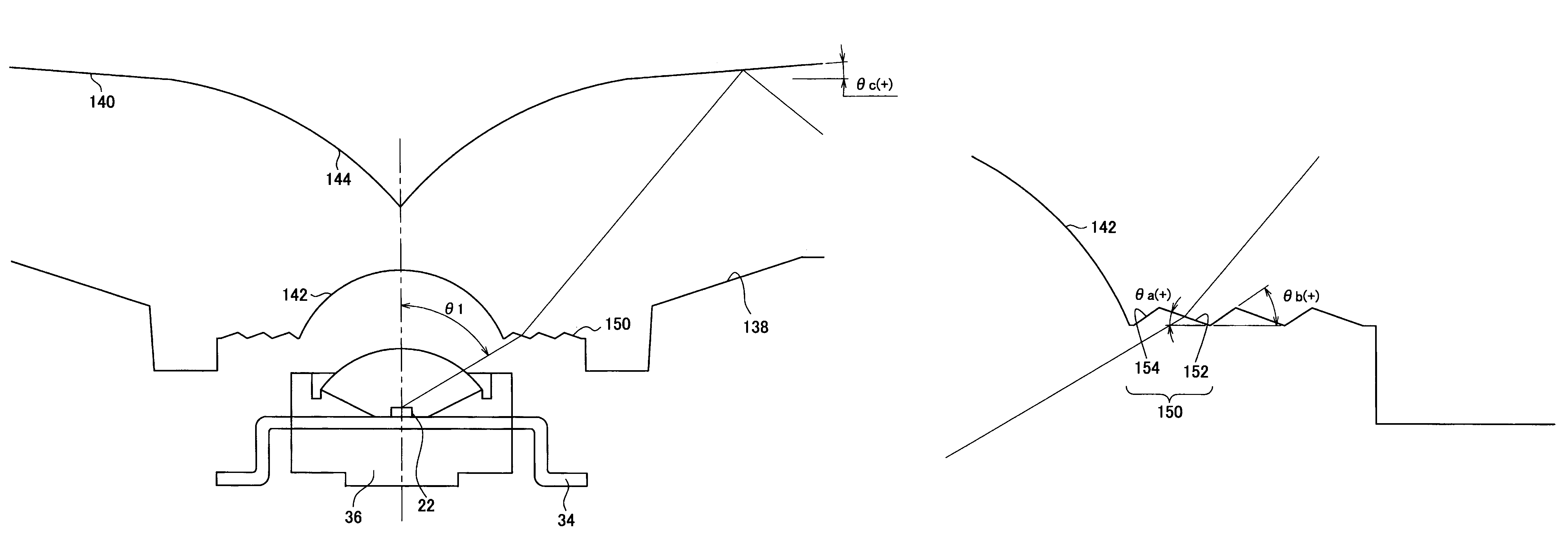
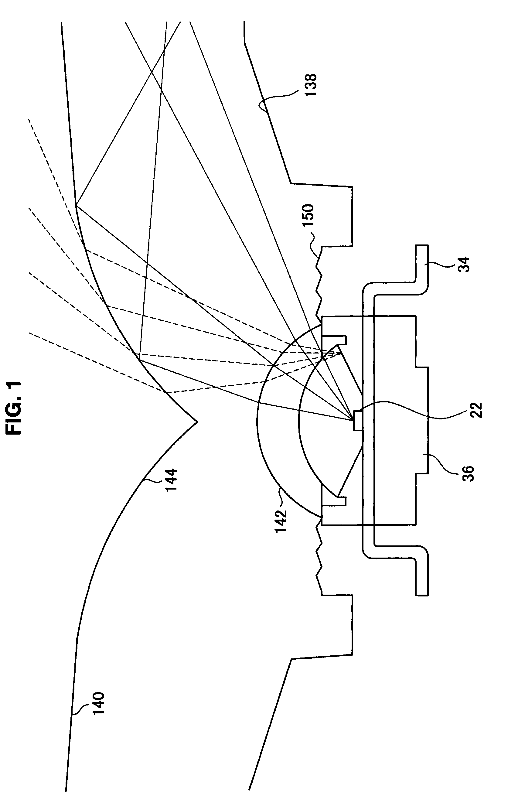
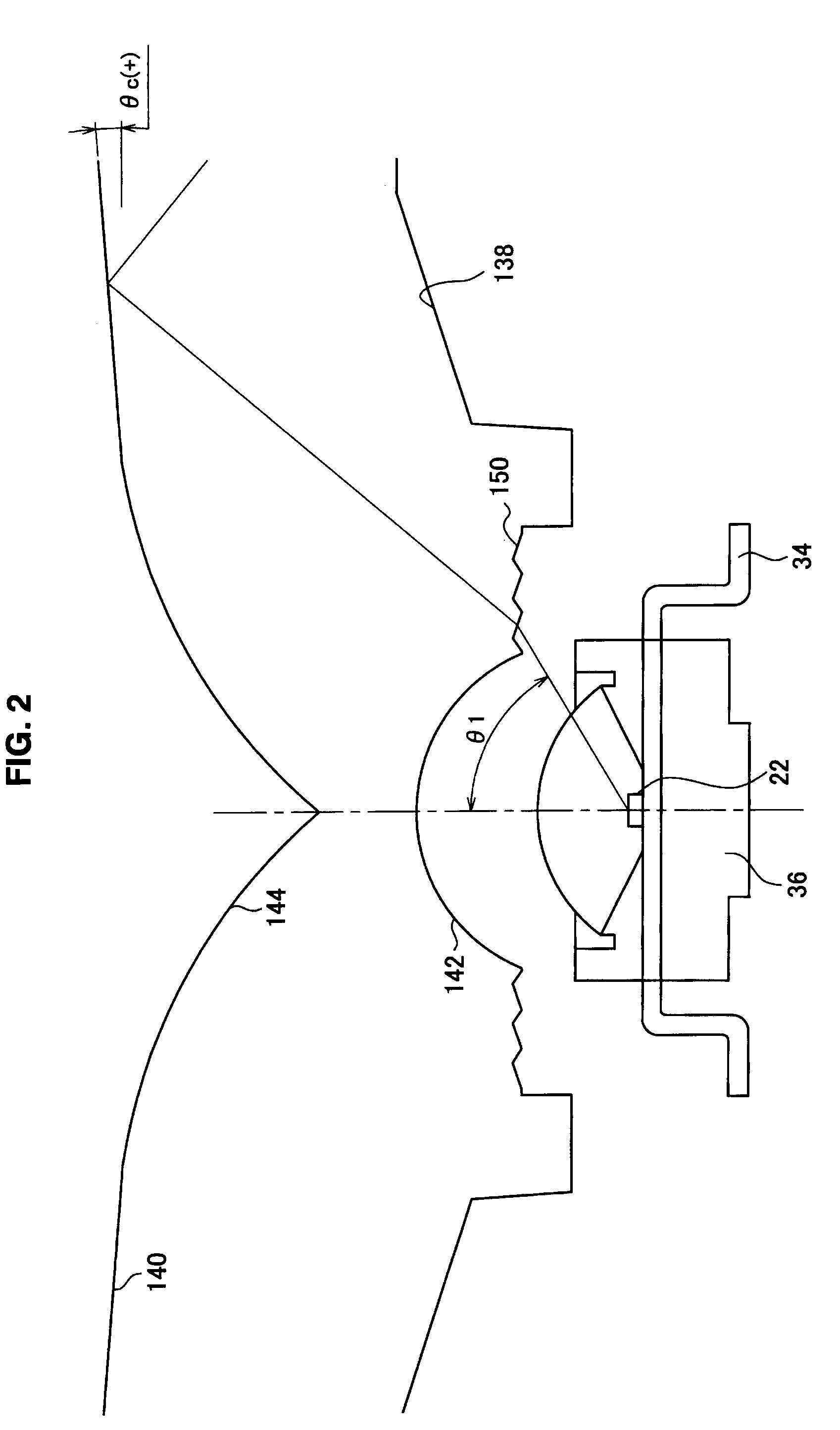
The present invention provides a light emitting apparatus and image displaying apparatus that can prevent a variation in luminance even when a LED is offset from a normal position. This is achieved by continuously forming irregularities on the light guide plate, which include a first slope and a second slope at a certain angle with the plane of the light incident face. The first slope is designed to fully reflect the light incident from the light source, while the second slope is designed to prevent the light from being directly refracted at the second slope and incident into the light guide plate. This results in a more uniform light output and reduced variation in luminance.

Problems solved by technology

However, there was an issue, in a light emitting apparatus in related art, that a variation in luminance is larger when a position of LED is offset from a normal position.
As described above, when the LED is offset from the normal position, a light exited from the LED is irregularly reflected within the light guide plate and then transmits a light exit face of the light guide plate, which causes an issue that a variation in luminance becomes larger.

Method used


Image

  • Light emitting apparatus and image displaying apparatus
  • Light emitting apparatus and image displaying apparatus
  • Light emitting apparatus and image displaying apparatus

Examples


Embodiment Construction

[0045]Hereinafter, preferred embodiments of the present invention will be described in detail with reference to the appended drawings. Note that, in this specification and the appended drawings, structural elements that have substantially the same function and configuration are denoted with the same reference numerals, and repeated explanation of these structural elements is omitted.

[0046]The explanation will be made in the following order.

[0047]1. Issues in the past[0048]1-1. Schematic configuration of typical image displaying apparatus 10[0049]1-2. Issues due to positional offset of LED 22 in light emitting apparatus

[0050]2. Schematic configuration of light emitting apparatus 100 according to one embodiment of the present invention

[0051]3. Solution of issues due to positional offset of LED 22 in light emitting apparatus 100

[0052]4. Simulation results

[0053]5. Conclusions

[0054]A light emitting apparatus 100 according to one embodiment of the present invention will be described in de...


PUM

PropertyMeasurementUnit
distanceaaaaaaaaaa
angle θaaaaaaaaaaa
angle θbaaaaaaaaaa

Abstract

A light emitting apparatus is provided which includes a plurality of light sources for emitting a light, and a light guide plate having a substantially plate shape orthogonal to the optical axis direction of the light source, which includes a light incident face into which a light exited from the light source is incident and a light exit face from which the light incident from the light incident face is exited. Irregularities each made of a first slope forming an angle θa with the plane of the light incident face and a second slope forming an angle θb with the plane of the light incident face are continuously formed on the light incident face.

Description

BACKGROUND OF THE INVENTION[0001]1. Field of the Invention[0002]The present invention relates to a light emitting apparatus and an image displaying apparatus.[0003]2. Description of the Related Art[0004]In recent years, in many cases, there has been utilized, along with an enlargement of size of a display panel, a backlight-type light emitting apparatus in which a plurality of light emitting diodes (LED) are arranged immediately below the display panel in an image displaying apparatus such as television receiver. The LED has the characteristic of more brightly lighting nearer the center of the LED due to its directivity characteristics. Thus, it is necessary to diffuse lights enough to illuminate the display panel and to reduce a variation in luminance in the display panel.[0005]A method for preventing a variation in luminance from occurring includes a technique described in Japanese Patent Application Laid-Open No. 2008-305642, for example. There is disclosed in Japanese Patent App...

Claims


Application Information

Patent Timeline
Patent Type & Authority Patents(United States)
IPC IPC(8): G09F13/04G02F1/13357
CPCG02B6/0016G02B6/0021G02F1/133603G02B6/0055G02B6/0078G02F2001/133607G02F1/133607
Inventor OHKAWA, SHINGO
Owner SATURN LICENSING LLC
Learn More