
Method and apparatus for effecting temperature difference in a respective zone

Active Publication Date: 2012-05-15
SAVE ENERGY SYST INC
View PDF13 Cites 67 Cited by
  • Summary
  • Abstract
  • Description
  • Claims
  • Application Information

AI Technical Summary

Benefits of technology

[0010]Hence, the demand limiting controller has “pre-cooled” the respective zone in anticipation of the peak rate time range. Since the demand limiting controller (i) cools the respective zone before the peak rate time range begins and (ii) sets the zone temperature above its pre-cool temperature once the peak rate time range begins, the demand limiting controller minimizes the use of electricity during the peak rate time range and lowers costs associated with power consumption.
[0011]In addition, the demand limiting controller continually updates the data describing amounts of time that occur between temperature changes as the temperature modification unit cools the respective zone. Hence, over time, the respective zone's cooling rate becomes more accurate in describing how much time is actually required to change the respective zone's current temperature depending on the outdoor temperature.
[0014]The demand limiting controller cools (or heats) the respective zone until it determines that another temperature modification unit associated with a different zone requires electricity either for “pre-cooling,” heating or to avoid the current temperature in that other zone from moving outside its respective target range. If another temperature modification unit needs to change the temperature in its corresponding zone, and the desired maximum amount of power is currently not being totally consumed, the demand limiting controller can allow for multiple temperature modification units to be running so long as the desired maximum amount of power is not exceeded.
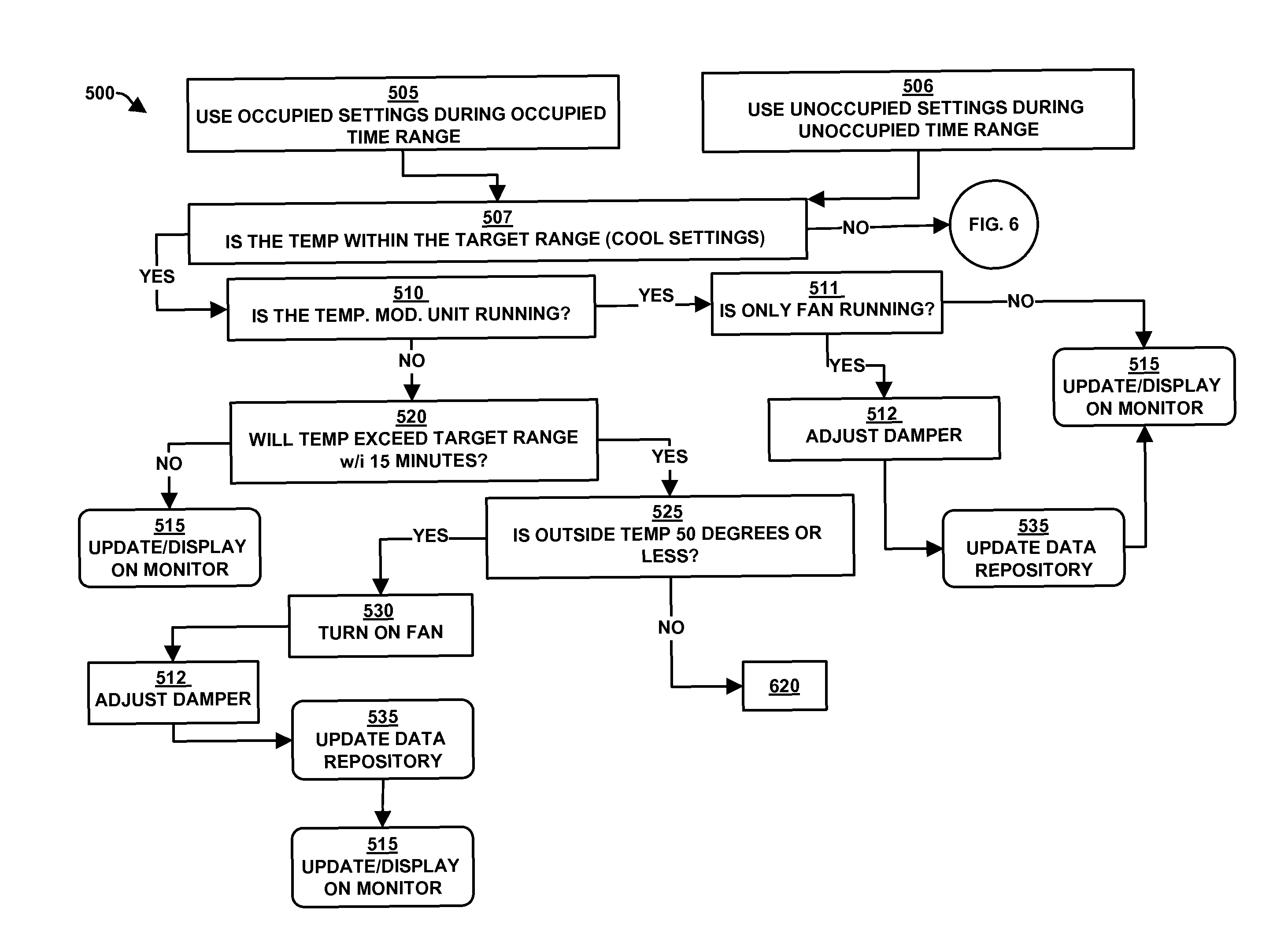
[0015]In yet another embodiment, some of the temperature modification units located amongst the multiple zones have a damper that provides natural, outside air to be ventilated throughout a respective zone. Thus, instead of consuming electricity by using a temperature modification unit to cool a respective zone, the demand limiting controller can cool the respective zone by allowing outside air in the respective zone.
[0017]As the respective zone's current temperature changes due to the newly-introduced outside air, the demand limiting controller can continually adjust the extent the damper is open. Thus, the demand limiting controller gradually closes the damper as the respective zone's current temperature approaches the target temperature. If the outside temperature in combination with the maximum volume of outside air is insufficient to cool the zone to the desired temperature, the demand limiting controller will energize the cooling portion of the temperature modification unit.

Problems solved by technology

Conventional systems that regulate and control one or more Heating, Ventilating and Air Conditioning (HVAC) units in a building or multiple refrigeration / freezer units in warehouse or retail environments suffer from a variety of deficiencies.
Also, such conventional systems are limited to continually monitor the temperatures of various internal spaces within a building but do not predict when a particular internal space's temperature will be outside of an acceptable temperature range with regard to the current outdoor temperature.

Method used


Image

  • Method and apparatus for effecting temperature difference in a respective zone
  • Method and apparatus for effecting temperature difference in a respective zone
  • Method and apparatus for effecting temperature difference in a respective zone

Examples


Embodiment Construction

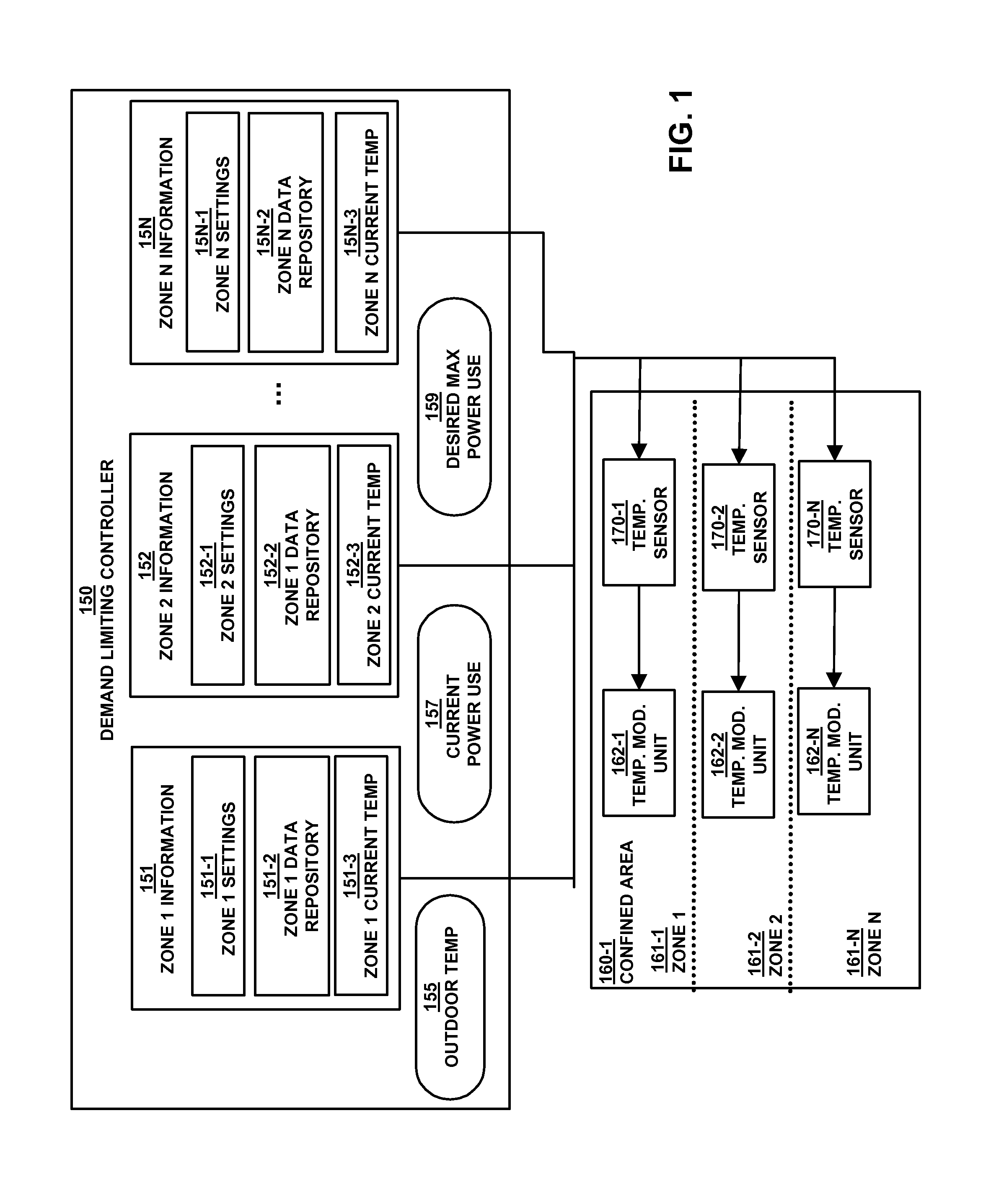
[0032]FIG. 1 is an example block diagram of a demand limiting controller 150 according to embodiments herein.

[0033]A confined area 160-1, such as a commercial, industrial, retail, office, residential or hotel building or a warehouse or a refrigeration / freezer unit(s), can be divided into multiple internal zones 161-1, 161-2, 161-N. Each zone 161-1, 161-2, 161-N can be an internal space within the confined area 160-1. Further, each zone 161-1, 161-2, 161-N is associated with a temperature modification unit(s) 162-1, 162-2, 162-N that can control the rate of the temperature change with a respective zone 161-1, 161-2, 161-N. It is understood that the confined area 160-1 can be divided into any number of zones across any number of buildings, warehouses or refrigeration / freezer units, and each zone 161-1, 161-2, 161-N can be associated with any number of temperature modification units.

[0034]The demand limiting controller 150 stores, manages and continually updates zone information 151, 1...


PUM


Abstract

Methods and apparatus provide for a demand limiting controller. The demand limiting controller obtains at least one temperature condition and at least one temperature modification rate associated with at least one respective zone from multiple zones of a confined area. The demand limiting controller determines when to modify a current temperature of the respective zone with respect to an upcoming event by processing the temperature condition according to the temperature modification rate while minimizing the opportunity for all zones to be energized simultaneously.

Description

BACKGROUND[0001]Air conditioning and refrigeration are provided through the removal of heat. Heat can be removed through the process of radiation, convection, and conduction using mediums such as water, air, ice, and chemicals referred to as refrigerants. An air conditioning system provides cooling, ventilation, and humidity control for all or part of a house, building or refrigerator / freezer. The refrigerant provides cooling through a process called the refrigeration cycle. The refrigeration cycle consists of four essential elements to create a cooling effect. A compressor provides compression for the system. This compression causes the cooling vapor to heat up. The compressed vapor is then cooled by heat exchange with the outside air, so that the vapor condenses to a fluid, in the condenser. The fluid is then pumped to the cooling zone, where it enters an evaporator. In this evaporator, small spray nozzles spray the cooling fluid into a chamber, where the pressure drops and the fl...

Claims


Application Information

Patent Timeline
IPC IPC(8): G01M1/38G05B13/00G05B15/00G05D23/00A47J39/00F25B29/00B60H1/00F24F3/00
CPCF24F11/0086G05D23/1934F24F2011/0075F24F11/30F24F11/46F24F11/64
Inventor LASKOW, PAUL IRA
Owner SAVE ENERGY SYST INC
Learn More