Fluid injection device

a technology of injection device and flue gas, which is applied in the direction of functional valve types, sealing/packing, and borehole/well accessories, etc., can solve the problems of reducing the life of the valve device, reducing the performance, and the known gas lift valve will not work as expected, so as to achieve less pressure loss and large flow area

Active Publication Date: 2012-05-22
GASOLINEEUM TECH
View PDF47 Cites 12 Cited by
  • Summary
  • Abstract
  • Description
  • Claims
  • Application Information

AI Technical Summary

Benefits of technology

[0004]An aim with the present invention is to minimize and possibly alleviate these problems. It is also an aim to provide a device with a true metal to metal sealing of the device. Metal to metal seal in a preferred embodiment is understood to be a single seal between two metallic surfaces without any secondary seal, soft seal or a combination of such. It is also an aim to provide a device with a reduced erosion rate of the sealing surface. Another aim is to provide a device with an increased flow area compared with similar known valves. There is a further aim to provide a device with minimal flow restrictions and disturbances in the injection flow, giving reduced pressure losses across the device. There is also an aim to provide a device with a low operating pressure difference.
[0016]According to another aspect the internal body comprises a stop surface which in a fully open position of the device is abutting against a corresponding surface (the nose) in the outer housing. This stop surface may be positioned on one end of the internal body close to the outlet of the device, preferably on an opposite side of the slots compared with an inlet for the injection fluid into the intended bore and thereby prevent vibration in the internal body of the injection fluid, in an open position of the device.
[0022]These features of the invention will provide a device where the flow path of the injection fluid is substantially less tortuous than other known gas injection valves due to the more direct flow through the bore in the internal body and directly out through the slots. This also gives less pressure losses across the valve. By designing the inlets, orifice, outlets and the slots of the device, one could achieve the desired effect with regard to flow pattern and cavitations. The present invention is also a simplified device with few elements, compared with the majority of other known injection valves. This gives a more reliable device as well. The present invention also has a relatively large flow area through the device; compared with the majority of other known injection valve of similar size.

Problems solved by technology

After a period of time, known gas lift valves will have a tendency of not working as expected.
One problem might be the erosion of the sealing surfaces of the valve device which lead to leakage across the valve seat and reduced performance and a reduced lifetime for the valve devices.
This creates a problem for operation of the well with increased down time, maintenance time and an increased safety hazard.

Method used


Image

  • Fluid injection device
  • Fluid injection device

Examples


first embodiment

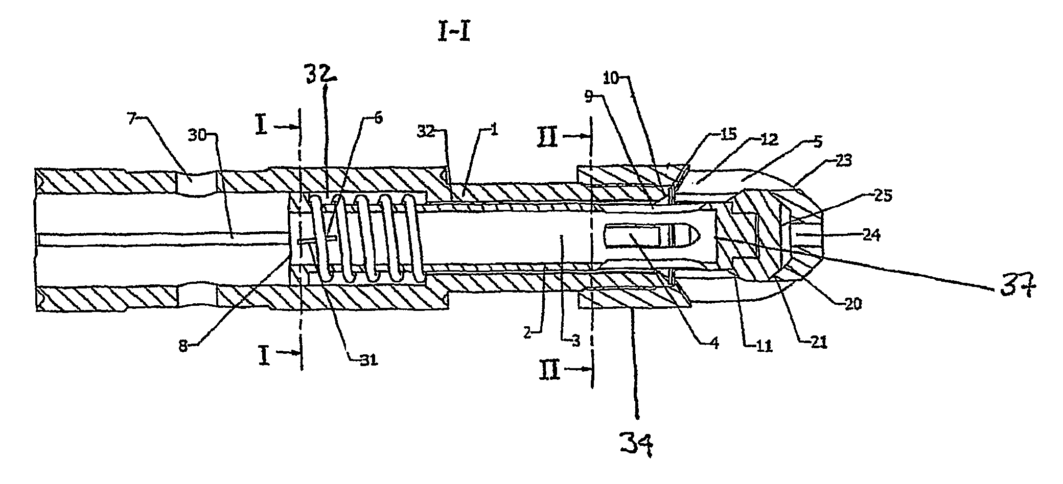
[0029]In FIG. 1 there is shown a device according to the invention. This embodiment is a gas lift valve for positioning in a well stream. A skilled person will understand how this is done and this is therefore not described in this application.

[0030]In the FIG. 1 the device, normally used as a gas lift valve, but the principle may be used for other kind of injection valves, comprises an outer housing 1 with an internal body 2 movable within the outer housing 1 between two positions. As can be seen in the figure, the outer housing in this embodiment comprises two parts, that is, the main part 1 and the nose 34. The nose 34 is connected to the main part 1 with suitable means, for instance as a threaded joint. An open position is shown in FIG. 1. The internal body 2 is movable in the longitudinal direction of the internal body 2 and outer housing 1. The outer housing 1 comprises injection fluid inlets 7 close to an end of the outer housing 1. These inlets 7 are in contact with an injec...

second embodiment

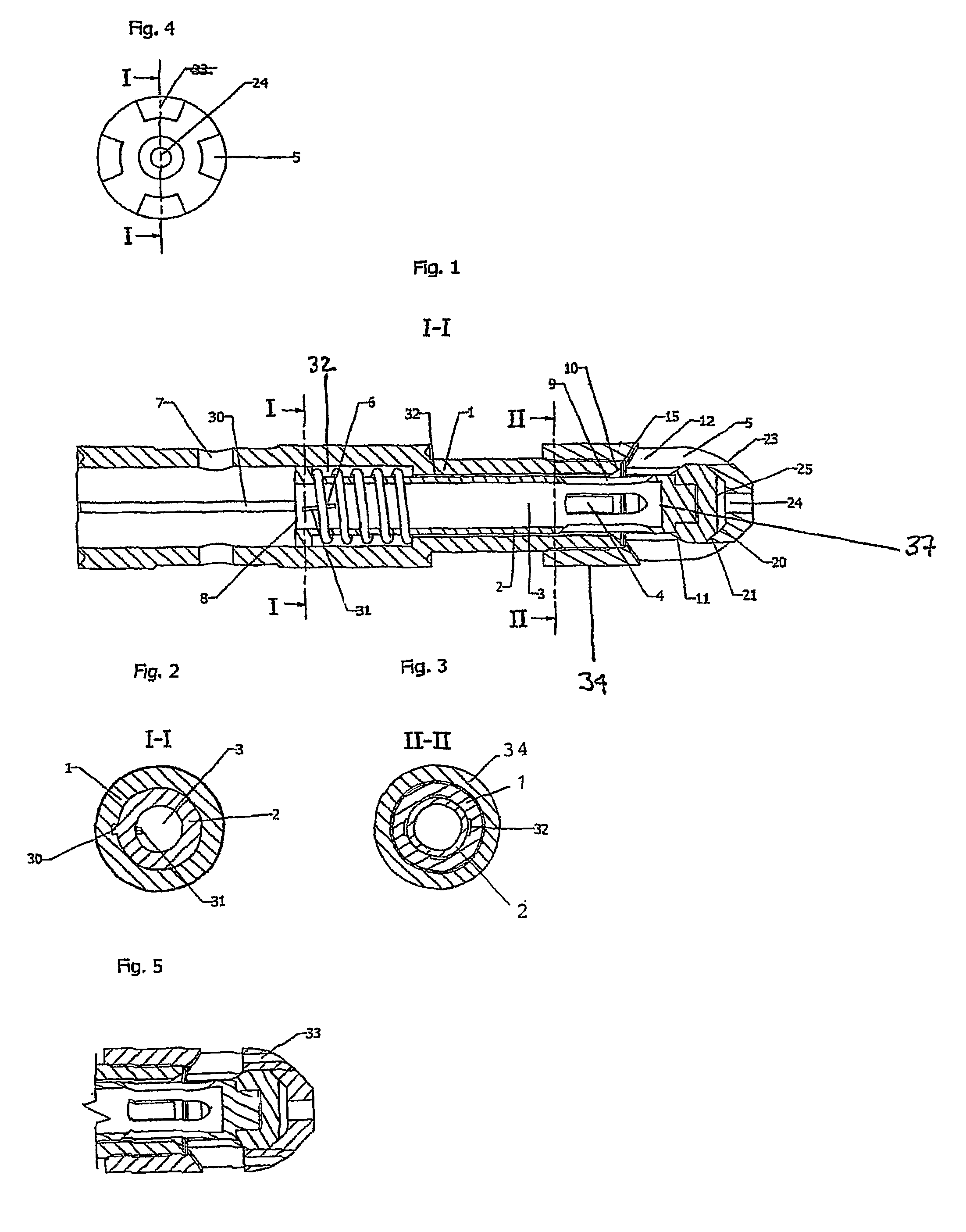
[0039]FIG. 5 is the cross section of the foremost part of the device, of the present invention and show the area around the slots 5 of the outer housing 1 where one or more through-going outlets 33 are arranged around the circumference of the outer housing. The outlets 33 are longitudinal, circular in form and mainly parallel with a longitudinal axis of the outer housing 1. The outlets 33 are further connected with the slots 5 and their function are to bring forth in the injected fluid the ability to penetrate the production flow in the tubing, thereby gaining a better incorporation of the injected fluid in the flow.

[0040]Only elements related to the invention is described and a skilled person will understand that an outer housing or internal body may be formed in one unit or be comprised of several connected elements, and that the inlets have to be connected to a source of the fluid to be injected, that there should be appropriate attachment devices for attaching the valve within a...


PUM


Abstract

The present invention regards a device designed for injection of fluids in a well bore, typically an offshore well bore for petroleum production and gas injection / gas lift system for fluid injection. The device comprises a outer hollow housing (1) with an internal body (2) moveable within the outer housing (1) with an internal bore (3) which in a first closed position is closed with a metal to metal seal system between the outer housing (1) and the internal body (2), which internal body (2) is operated by pressure differential across the internal body (2), where the internal body (2) is designed with slots (4) forming outlets of the internal bore (3) which in an open position of the device leads to the outside of the outer housing (1).

Description

FIELD OF THE INVENTION[0001]The present invention regards a device for injection of fluid in a well bore, typically an offshore well bore for petroleum production and gas injection / gas lift system.BACKGROUND[0002]There are known several different principles of operating a gas injection valve, one of this is based on the venturi principles, for instance described in WO 2004 / 092537 A1. Another approach is to have a central stem with outer sealing surface and through going flow between an outer housing and the central stem across the sealing surfaces, for instance described in CA 02461485 A1.[0003]After a period of time, known gas lift valves will have a tendency of not working as expected. One problem might be the erosion of the sealing surfaces of the valve device which lead to leakage across the valve seat and reduced performance and a reduced lifetime for the valve devices. This creates a problem for operation of the well with increased down time, maintenance time and an increased ...

Claims


Application Information

Patent Timeline
Patent Type & Authority Patents(United States)
IPC IPC(8): E21B34/04E21B34/08
CPCE21B43/123Y10T137/7925
Inventor TVEITEN, MAGNARSTOKKA, OYVINDKLEPPA, ERLINGNORLAND, TOM
Owner GASOLINEEUM TECH
Why Eureka
Try Eureka