Flow pulsing device for a drilling motor

a technology of flow pulsing and drilling motor, which is applied in the direction of drilling machine and method, drilling accessories, core removal, etc., can solve the problems of limited pulse capacity, limited advancement of drill string, and limited amount of pulsing, so as to achieve the effect of easy adjustmen

Active Publication Date: 2012-05-22
TARTAN ENERGY GRP INC +1
View PDF7 Cites 42 Cited by
  • Summary
  • Abstract
  • Description
  • Claims
  • Application Information

AI Technical Summary

Benefits of technology

[0010]By providing a valve with a drive link member connected thereto which permits connection of the valve directly to the drilling motor, the flow pulsing device is simple in construction having a minimum number of components which can be installed at any point in the drill string above the drilling motor. The direct coupling of the flow pulsing valve to the rotor permits the valve to be maintained in a reliable manner out of synchronicity with the natural vibration of the drilling motor to maximize the amplitude of the vibrations produced with a simple reliable structure.
[0020]By further providing a fixed valve portion which is adjustable in a longitudinal direction relative to a rotating component of the valve, an amount of fluid which bypasses the valve relative to the intermittent flow passage of the valve allows the amplitude of the vibration to be readily adjusted in the field unlike prior devices.

Problems solved by technology

When drilling an oil or gas production well using a drill string, it is common to encounter static friction that limits advancement of the drill string into the bore being formed.
As the rotating valve component is directly driven by vanes coupled thereto, the amount of pulse capable is limited.
Furthermore in some embodiments a bypass area is provided, however the bypass area is proportionally very large compared to the pulsing component so as to further limit the amount of pulsing possible.
Walter, U.S. Pat. No. 4,819,745, discloses a further example of a flow pulsing device in which the rotating component of the valve creating the pulses is driven by an impeller with vanes integrally associated therewith so that the overall structure of the integrated valve and impeller is very complex and can therefore have problems with reliability.
The direct coupling of the impeller with the rotating valve component may also limit the amount of pulsing possible.
The overall assembly of a flow pulsing valve together with a motor operated solely for rotating the valve is a costly and complex structure to be installed in a drill string separate from the drilling motor.

Method used


Image

  • Flow pulsing device for a drilling motor
  • Flow pulsing device for a drilling motor
  • Flow pulsing device for a drilling motor

Examples


Embodiment Construction

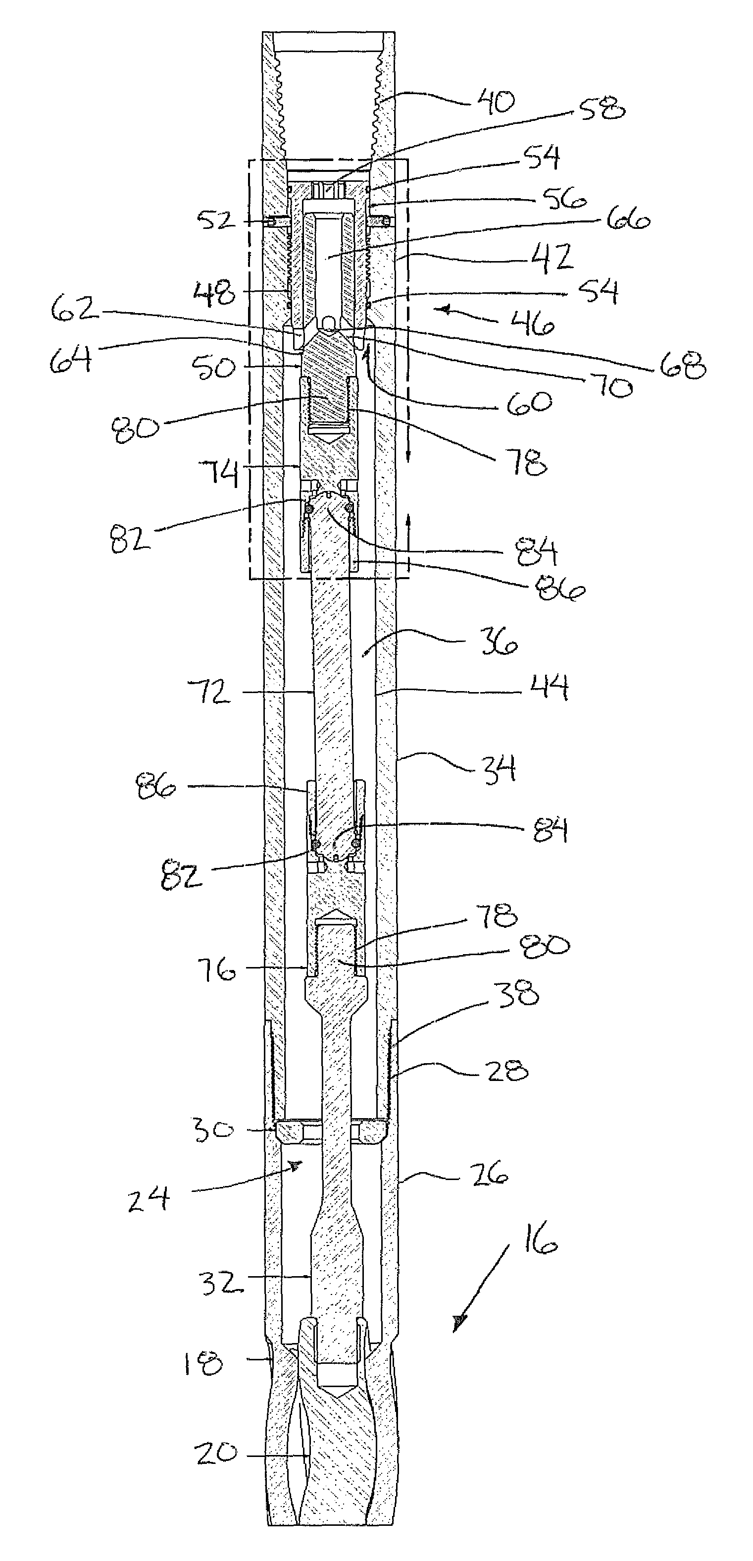
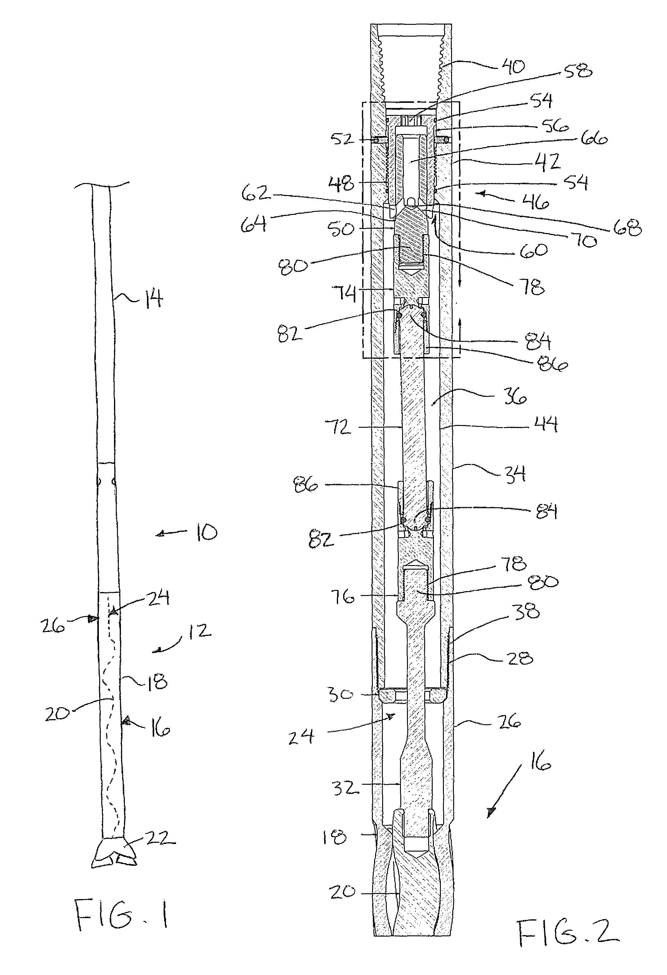
[0036]Referring to the accompanying figures there is illustrated a flow pulsing device generally indicated by reference numeral 10. The device 10 is particularly suited for use with a drill string 12 of the type connected to the bottom end of a tubing string 14 in a well bore being formed.

[0037]The drill string comprises a drill motor 16 coupled to the bottom end of the tubing string which further comprises a stator housing 18 connected in series to the tubing string 14 and a rotor 20 rotatably received within the stator housing. The stator housing and the rotor have complimentary lobes to force to rotation of the rotor 20 relative to the stator housing responsive to a flow of drilling fluid pumped into the drill motor from the tubing string 14. The drill motor 16 thus comprises a progressive cavity positive displacement motor which rotates a drill bit 22 of the drill string which is coupled to rotate with the rotor 20 at the bottom end thereof. Suitable rotor bearings are provided ...


PUM


Abstract

A downhole flow pulsing device comprises a housing connected in series with a drill string and a valve with a rotating portion in the housing arranged to vary an area of a flow passage through the housing. A fluid actuated positive displacement motor drives rotation of the valve. A drive link permits the rotating portion of the valve to be optionally coupled directly to the motor of the drill string. The valve includes radially oriented rotating ports intermittently communicating with surrounding fixed ports and a bypass channel. Axial displacement of the rotating ports relative to the fixed ports and bypass channel permits amplitude of the downstream fluid pulses to be adjusted. The valve includes a number of circumferentially spaced ports which differs from a prescribed number of pressure fluctuations in the fluid for each full rotation of the rotor of the drill motor.

Description

FIELD OF THE INVENTION[0001]The present invention relates to a flow pulsing device arranged to pulse drilling fluid of a drilling motor in a drilling string.BACKGROUND[0002]When drilling an oil or gas production well using a drill string, it is common to encounter static friction that limits advancement of the drill string into the bore being formed. In these instances it is known to be desirable to pulse the flow of drilling fluid pumped through the drill string to vibrate the drill and reduce the static friction so that deeper wells can be more readily produced. Examples of prior United States Patents relating to pulsing the flow of drilling fluid include U.S. Pat. No. 6,279,670 by Eddison et al; U.S. Pat. No. 4,819,745 by Walter; and U.S. Pat. No. 2,743,083 by Zublin.[0003]In Zublin, U.S. Pat. No. 2,743,083, various embodiments are disclosed in which a rotating valve component is driven to rotate by suitable vanes coupled thereto or by the orientation of the flow passages thereth...

Claims


Application Information

Patent Timeline
Patent Type & Authority Patents(United States)
IPC IPC(8): E21B4/02
CPCE21B4/02E21B7/24E21B21/103
Inventor BUNNEY, LARRY RAYMONDLISOWSKI, TREVOR NICHOLAS STANLEY
Owner TARTAN ENERGY GRP INC
Why Eureka
Try Eureka