Vibration damper

a technology of vibration damper and damper body, which is applied in the direction of shock absorber, piston pump, positive displacement liquid engine, etc., can solve the problems of most of the energy to be absorbed, further damage or injury, etc., and achieve the effect of improving the safety of the system

Active Publication Date: 2012-05-22
EDWARDS LTD
View PDF23 Cites 10 Cited by
  • Summary
  • Abstract
  • Description
  • Claims
  • Application Information

AI Technical Summary

Benefits of technology

[0010]In practical terms, the permitted magnitude of the extension of the damper is governed by the flexibility of the bellows, the space available in the location of the apparatus and the flexibility of the peripheral equipment attached to the vacuum pump. This is typically 5 to 10 mm. Since the magnitude of the static force exerted on the pump is also predetermined, the stiffness characteristic of the damper is restricted. In the simplest, the relationship between force and displacement may be linear as shown at 19 in FIG. 6 such that the stiffness has a constant value. In known prior art systems as discussed above, the mechanical support is formed from an elastomeric material. Such materials have a hyperelastic load / deformation relationship such that they have a progressive stiffness characteristic. This type of relationship is represented at 20 in FIG. 6. It can be seen that in the typical loading regime (denoted F) the stiffness curve 20 has become steep indicating an increased value of stiffness. It is desirable that the stiffness characteristic associated with the damper, when loaded, is small by design, as represented at 18 in FIG. 6, such that transmission of vibration to the apparatus is minimised. However, overall permitted extension of the damper 1 is predetermined as discussed above, so pre-compression of the damper prior to installation between the apparatus and the pump can provide a much higher stiffness characteristic at lower displacement, represented at 17 in FIG. 6, such that the required applied load can be borne by the damper whilst not exceeding the extension limits. Therefore, a mechanical support of much lower stiffness, and consequently better vibration transmission properties, can be provided.
[0013]It is, therefore, a further object of the present invention to provide a vibration damper that inhibits any such rotational movement of the vacuum pump and, consequently, enhances safety of the system.

Problems solved by technology

A further problem associated with known vibration dampers is that in the event of pump failure through rotor seizure, they provide an inherent weakness which can be of safety concern.
In some circumstances, the rotor blades are stripped from the rotor thus causing most of the energy to be absorbed as the destruction and deformation of the internal components occurs, and hence the failure can be contained within the pump housing.
However, in some pumps, such as those with a bell shaped rotor, the rotor is likely to be split into a small number of sections, each section having a significant quantity of rotational momentum with a large impulse.
Conventional vibration dampers have minimal resistance to such rotational loading and are damaged, resulting in the pump becoming detached from the apparatus and causing further damage or injury.

Method used


Image

  • Vibration damper
  • Vibration damper
  • Vibration damper

Examples


Embodiment Construction

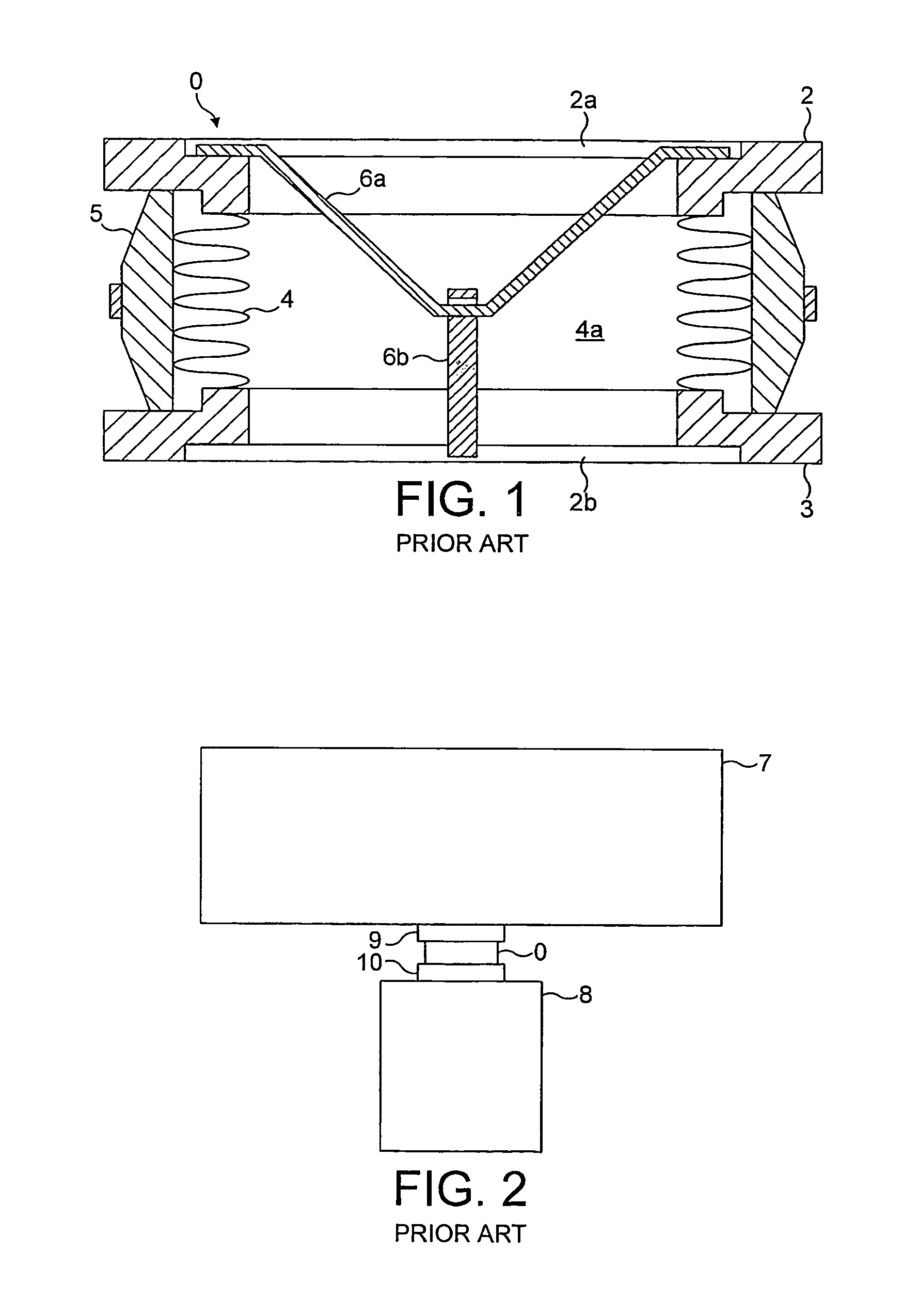
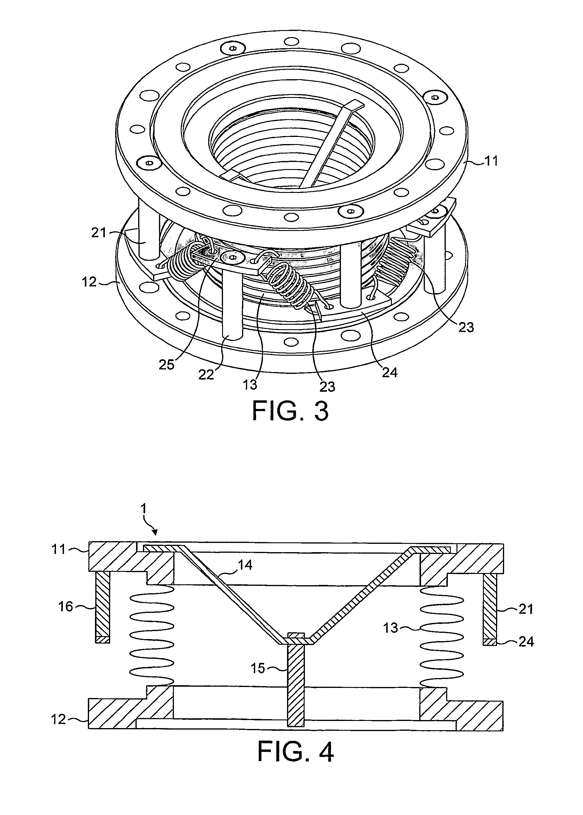
[0027]FIG. 2 illustrates a generic vacuum system which is suitable for incorporating a vibration damper 1 of the present invention. As such, references will be made to components shown therein, in combination with subsequent drawings.

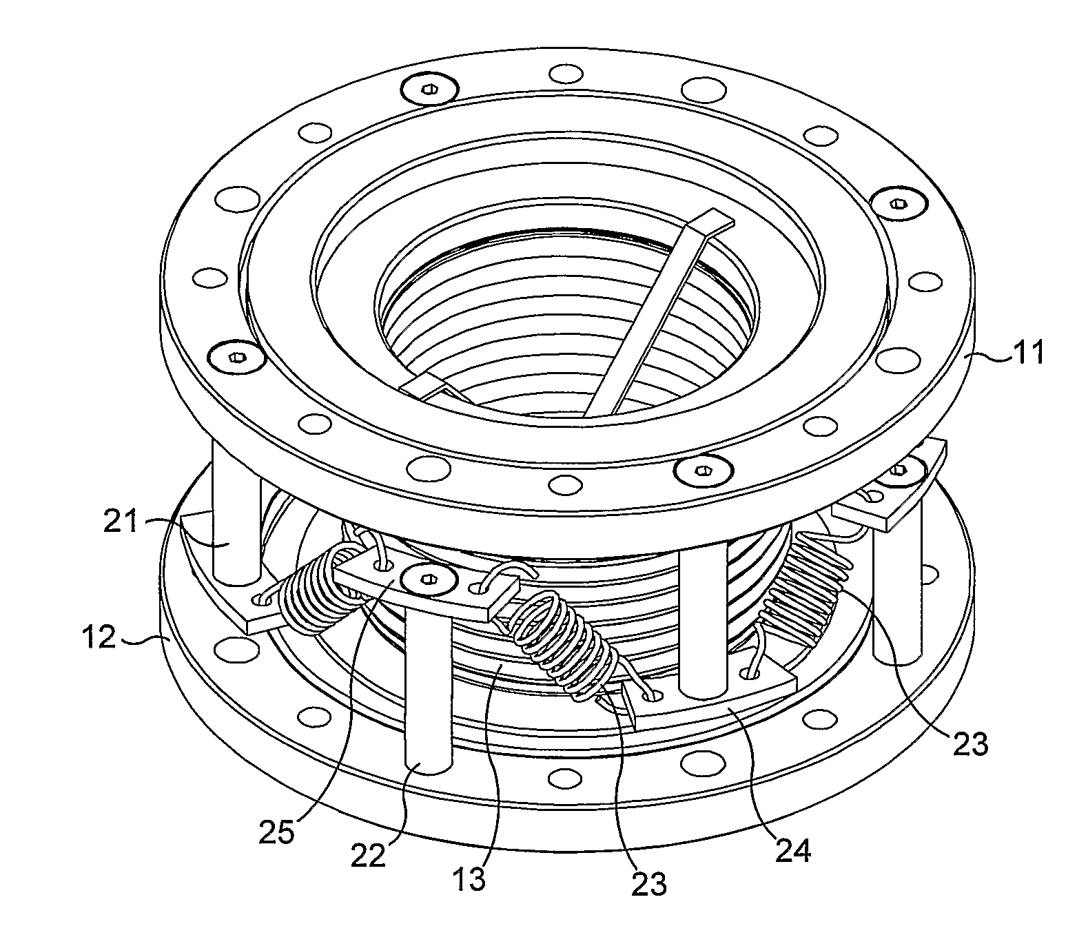
[0028]As shown in FIGS. 3, 4 and 5, vibration damper 1 comprises a first flange 11 for connecting the damper 1 to a flange of the fluid exhaust 9 of the apparatus 7 and a second flange 12 for connecting the damper 1 to fluid inlet 10 of the vacuum pump 8. The damper 1 further comprises a compliant gas barrier or shield 13, such as a convoluted bellows of a generally cylindrical form connected with a gas tight seal at either end to respective flanges 11, 12 in order to define a fluid flow path from the apparatus 7 to the vacuum pump 8. Within the confines of the bellows 13, two interlinking V-shaped straps 14, 15 are provided. One strap 14 is welded at either end to the first flange 11 at diametrically opposed positions. The other strap 15 is welded at e...


PUM


Abstract

A pre-compressed vibration damper is provided for inhibiting transfer of vibration to an apparatus during the evacuation thereof by a pump.

Description

FIELD OF THE INVENTION[0001]The present invention relates to vibration dampers.BACKGROUND OF THE INVENTION[0002]Vibration dampers are used to reduce the vibration transmitted from a high-vacuum pump, for example, a turbomolecular pump, to apparatus to be evacuated during a pumping operation. Vibration dampers are particularly advantageous when vacuum pumps are used to evacuate apparatus which is sensitive to mechanical vibration. For example, vibrations transmitted to an evacuated Scanning Electron Microscope could lead to inaccuracies in measurements being taken by the microscope, and vibrations transmitted to a process tool could cause anomalies in products being manufactured within.[0003]With reference to FIG. 2, a vibration damper 0 is typically connected between the fluid exhaust 9 of the apparatus 7 to be evacuated and the fluid inlet 10 of the vacuum pump 8. FIG. 1 illustrates the configuration of a known vibration damper 0 in more detail. The damper 0 includes two flanges 2,...

Claims


Application Information

Patent Timeline
Patent Type & Authority Patents(United States)
IPC IPC(8): F16M1/00F16M13/00F04D29/66F16F15/04F16F15/067F16L27/11
CPCF04D29/668F16F15/067F04D19/04
Inventor BREWSTER, BARRIE DUDLEY
Owner EDWARDS LTD
Why Eureka
Try Eureka